In this article I have explained a very simple method of acquiring 220V DC from a 12V DC source. The idea utilizes inductor/oscillator based boost topology with the help of the IC 555.
Circuit Operation
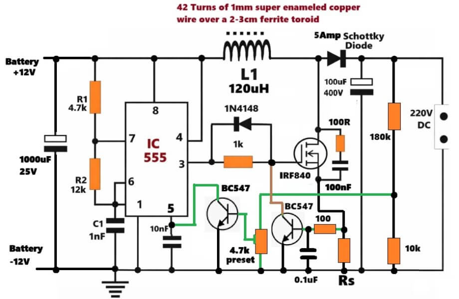
Now let us learn more about this simple 12V to 220V DC boost converter circuit, which is built around IC 555, one IRF840 MOSFET, one inductor, and then a few transistor parts for feedback side.
It is made to boost a low 12V DC input into a much higher DC output, somewhere near 220V DC, by fast inductive switching...
555 IC Astable Frequency Generator
If you look at the circuit diagram on the screen, then the left side starts with IC 555 working as an astable oscillator. In that area, R1, R2, C1 decide the switching frequency of the integrated circuit.
IC 555 keeps sending rectangular pulses from pin 3, and that pulse becomes the switching drive for the mosfet.
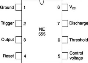
Pin 8 and pin 4 go to the +12V line, while pin 1 goes to ground. Pin 5 is connected to ground through a 10nF, which helps keep the integrated circuit quiet from switching noise, so it stays stable.
The pulse coming from pin 3 passes through 1k resistor before reaching the gate of IRF840. That resistor limits gate charging current and also saves the output side of IC 555.
1N4148 diode is placed around that gate path, so when the pulse goes low then the gate can discharge faster. Because of that the mosfet turns off quicker and switching loss stays lower.
MOSFET Switching
Now IRF840 is the main switching part here. It turns on and off again and again following the pulse from IC 555. When it turns on, then current starts moving from twelve volt supply through L one and then through the mosfet to ground. During that small on time, L1 stores energy inside its magnetic field.
When the mosfet turns off, then that magnetic field inside L1 collapses and throws a high-voltage reverse pulse.
That pulse appears at the drain side of the mosfet and then goes through the 5 ampere Schottky diode into the output capacitor.
Because this keeps repeating, the capacitor slowly charges and reaches high direct current voltage near two hundred twenty volts.
L1 is the Main Boosting Component
L1 is actually the part doing the voltage BOOSTING work, so its quality matters a lot. A ferrite core inductor works better here. A practical winding can be around forty to forty-five turns of one millimeter copper wire on ferrite rod or ferrite toroid core, which usually gives proper response.
The capacitor here is 100 microfarad rated at 400 volts, and it stores that boosted energy while also smoothing the output side.
Automatic Output Voltage Control
Now let us see the automatic voltage control side also.
At the output, 180K resistor and 10K resistor make a voltage divider. That divided voltage goes to the base of the shown BC547 transistor. This transistor keeps watching output voltage.
If output rises above the set level, then the left BC547 transistor turns on and grounds pin 5 of IC 555, executing PWM control, which limits further voltage rise. The 4.7k preset is there so you can adjust carefully and bring output near two hundred twenty volts.
Automatic Output Overload Protection
Now if we want overload control also, then one current sensing resistor marked RS can be added as shown. When output current increases, then voltage develops across RS and switches the right side BC547 transistor on, which grounds the MOSFET gate.
So now current limiting starts and mosfet gets protection during overload. 100 ohm resistor and 0.1uF capacitor there help steady the sensing action and reduce switching spikes.
We can also see one snubber network across drain and source of the mosfet, made using one 100 ohm and 0.1uF high-voltage capacitor. That part absorbs sharp spikes, so mosfet reliability improves.
This is Only a Low Watt Converter
In practical use, this circuit is only for small high-voltage jobs. Output power usually stays around five watts to fifteen watts, depending on inductor quality, switching frequency, and how strong the input supply is.
Ideally one 7 ampere-hour 12 volt battery or more works better, because weak adapters often fail when sudden current pulses are demanded by L one.
Caution
Please remember, although input is only twelve volts, output reaches dangerous high-voltage direct current. High-voltage direct current can be more dangerous than alternating current, because it does not naturally cross zero, so before touching the circuit always discharge the output capacitor.
Circuit Diagram
WARNING: THIS CIRCUIT INVOLVES HIGH VOLTAGE, EXTREME CAUTION IS ADVISED WHILE HANDLING THIS CIRCUIT.
IC 555 Pinout Details
Audio/Video Representation
How to Calculate all the Parts (For 1 Amp 220V Output)
Let's assume the maximum output current required is 1 Amps.
So 220V * 1A = 220W output.
From 12V battery, ohh so now we see the problem already.
Even if we assume 85% efficiency, which is optimistic, yep a little hopeful.
Pin ≈ 220 / 0.85
≈ 259W
Input current then becomes:
Iin ≈ 259 / 12
≈ 21.5A
So now our inductor L1 and MOSFET must survive that, and if current rises then it must not panic.
Around 25A peak current...
Around 220V drain voltage..
This is not small but maybe possible if parts are seriously selected.
Now duty cycle, which is the main issue here.
For boosting:
D = 1 − (Vin / Vout)
= 1 − (12 / 220)
= 0.945
So now 94.5% duty cycle, which means if duty goes that high then stress also goes high, that is the real heat generation issue here, on the MOSFET.
Now 5555 astable working with 50kHz, let us see.
Formula:
f = 1.44 / ((R1 + 2R2) * C1)
Choose C1 = 1nF.
50000 = 1.44 / ((R1 + 2R2) * 1e-9)
Then:
(R1 + 2R2) ≈ 28.8k
So we take:
R1 = 4.7k
R2 = 12k
Check:
R1 + 2R2 = 4.7k + 24k
= 28.7k
Close enough right... so frequency comes near 50kHz, that looks fine...
Now inductor, which is hugely critical, so lets pay attention here.
Input current ≈ 21.5A.
If ripple is 20%, then ΔI ≈ 4A.
Boost formula:
L = (Vin × D) / (ΔI × f)
L = (12 × 0.945) / (4 × 50000)
L ≈ 56 µH
So L1 equal around 56 µH.
Current rating must be 30A or more.
Use good Ferrite core only, since if core is weak then saturation quickly happens, killing the MOSFET.
DCR very low, below 10 milliohm if possible.
If inductor saturates then MOSFET dies instantly, without warning...
Now MOSFET side.
Ipeak ≈ 21.5 + 2
≈ 23.5A
But if spikes come then you can design for 30A minimum.
Voltage rating should be at least 500V.
IRF840, which does not look good here.
Rds(on) ≈ 0.85Ω.
Loss:
P ≈ I²R
≈ 20² × 0.85
≈ 340W during ON time
Even if duty scaling reduces average, still too much heat, it will overheat badly.
So we need:
500V 30 Amp MOSFET
Rds(on) below 0.3Ω ideally
Big heatsink, not small toy one
If one device struggles then parallel two, but layout must be tight, otherwise sharing goes wrong.
Please Use FQD20N60 or FCPF20N60 for the MOSFET.
Now about the diode.
It must handle 1A average output, but peak pulses go 20–25A.
Reverse rating at least 400V, but safer is 600V.
Ultra-fast diode is mandatory, since if recovery is slow then losses rise.
Schottky diode ultra-fast 600V diode is practical choice.
Now let's check real world situation..
220W from 12V boost is possible, but stressful.
Efficiency maybe 75–85% best case.
Copper tracks must be thick, since if tracks are thin then heating happens.
Cooling must be serious.
Note: This is not a small hobby circuit, it becomes power hardware.
Now Even at 1A output, frequency is not main issue.
The real issue is 94.5% duty cycle.
Only 5.5% OFF time exists, and if energy must transfer in that small window then current spikes grow huge, That can creates high peak currents and heavy switching stress.
That is why industrial designs do not boost 12V straight to 220V in one stage at high power.
They use transformer-based topology, since then stress spreads better.
So now safe recommendation.
With 555 boost style:
220V at 200mA–300mA, around 50W–60W, comfortable zone.
1A, which is 220W, possible but becomes aggressive, so make sure parts must be strong.
Above all that, 1 amp at 220V might not be practical, you will fight MOSFET heating and failure, sorry that is reality.


Questions & Answers
It will be difficult for me to identify exactly how you fixed the mosfet, I hope you've put it correctly.
What kind of inductor did you use and is your IC generating the required high frequency?? these two factors determine the correct operating conditions for the circuit.
Qual seria a função do DIODO ZENER , no circuito ?
If the output voltage exceeds the zener value, the zener conducts and switches ON the BC547, which in turn switches OFF the mosfet ensuring that the output never exceeds the value of the zener voltage
I would like Mr. Swagatam engineer
to teach me how to put a feedback circuit
with photo coupler in an inverter output equal to 127vac
the feedback circuit will monitor this voltage of 127vac
and make sure that it never drops or changes in any way always form
127vac and never change. Mr. could be showing here
through an article
– CI USED = SG3525
– PHOTO USED = PC817
Endel, you can refer to the following post!
The first 3 circuits, all have a feedback control, but without an opto coupler. Opto coupler can be difficult to set, so no opto couplers are used.
https://www.homemade-circuits.com/sg3525-pure-sinewave-inverter-circuit/
hello again,
i need to make a just opposite project converting 220v AC to 12v/24v DC help me please or please give me link of the same 🙂
Yes you can use a DMM which has a frequency feature in it.
Please refer to this post, it has all the details:
https://www.homemade-circuits.com/2013/05/55v-110a-n-channel-mosfet-irf3205.html
It would be dangerous to use the above type of configuration for your requirement, you may try the following design:
https://www.homemade-circuits.com/2013/06/0-300v-variable-voltage-current.html
Your DMM should have a frequency measuring option, normally indicated with "kHz" symbol, otherwise it won't help.
In response to the 555 frequency triggering, when the mosfet is in the ON state, the inductor stores the specified amount of electrical energy in it and during the mosfet OFF state reverts it to the output. This back emf from the coil constitutes the 220V at the ouput…
you can use the square wave symbol range for checking the frequency operation of the circuit…..
if it's not working with a mosfet you can try a transistor instead, try a TIP122.
this is an open source of Quantum telepotational electrical entanglimentals circuit resaunance pradox well done swagatam where advannce of mechanical stress will reverse as infinit power in the futures! your devotion is one of Quantum logic swagatam.
Hi Sir, sorry to ask this question here as I could not find a dc to dc step up circuit in your forum. I am thinking is it possible to modify this circuit to step up 2vdc to 12vdc? Thank you.
Hi Unknown,
the above circuit will require a minimum of 4V to operate correctly, I think you should try the following circuit, might just work:
https://www.homemade-circuits.com/2012/10/1-watt-led-driver-using-joule-thief.html
Dear sir ,
I have a battery 12v 32ah sf sonic jet , how can i charge by home made circuit ,I would like to use it as 200 Watt CFL inverter, kindly help me to making a 3 amp constant current battery charger,
thanking you,
Jayanta Roy
Bonjour Monsieur.
Pour le transistor mosfet il faut celui qui peut supporter une tension de 220V ?
Dear Jayanta,
You can try the second circuit shown in this link, but I am not sure about the transformer details you may have experiment with its size and wire gauge:
https://www.homemade-circuits.com/high-current-10-to-20-amp-automatic/
Thank you sir, I had tried joule before but the problem is the current supply is not high enough.I need at least 100mA. Can I know how to increase the current or is there any way to do it?
Use parallel wire winding, meaning use two or three wires together and then wind them as per the data, this will increase the current of the transformer,also you will have to use more number of cells in parallel for supplying the required amount of current.
okay sure i will try that and see what is the result, Thanks again sir.
Obaid just take out 220V AC, add a step down transformer that makes it 24V and then add a bridge rectifier and two filter capacitors electrolytic 10uF 25V and a 7812 IC, u'll get 12V
Hello Sir,
How can i modify this circuit to run a 150 or 100W fan.
Thank you in advance.
Rashid
Hello Rashid,
you will have to modify the coil by experimenting a little with the no of turns and wire gauge until it satisfies the conditions.
Thank you sir for your reply, I'll try it.
Rashid
sir can i use the polyester fluorescent ballast for inductor…
It will depend on the output voltage requirement, if the inductor is able to produce it then it would be fine.
Hi Swagatam
I am considering to use this transformerless circuit to provide high voltage in CDI. Any comments/modifications?
Hi Abu-Hafss,
Yes, it's worth trying.
Hi Swagatam
As per my usual practice, I have simulated this circuit and got following findings;
The frequency is 510Hz. If it is decreased to 50-100Hz, the output becomes more than 1kV.
The inductor is 250µH. The capacitor is 10µF.
Following is the wave pattern:
There is one issue i.e. how do we convert it to 230VDC? The CDI capacitor needs HV DC for charging which is provided thru a diode (half wave rectification) but, this output cannot be rectified, neither thru half wave rectification nor full wave.
If the capacitor value is increased, the output decreases.
Hi Abu-Hafss,
You can experiment with the number of turns of the inductor for getting different voltage levels at the output, because that's the only component that is directly related with voltage boosting.
Hi Swagatam
The out put is sort triangular waves of AC 230V (fluctuating between 0-230V not between 230 and -230 at 510Hz. How do we convert it to DC??? Single rectifier or bridge rectifier is not working, the output remains the same.
Maybe, the simulator is experiencing some difficulties in performing the rectification. Based on your experience, if you simulate in your mind, do you think the rectifier/capacitor should work to give a smooth DC output?
Hi Abu-Hafss,
Just connect a couple of 10uF250V(in parallel) across the output, no diodes are needed.
Hi Swagatam
Can this circuit be used to power a 30-40W soldering iron?
If yes, would 12V-5A input be enough?
Hi Abu-Hafss,
yes it can be used, 12v/5amp would be just enough for that.
Hi Swagatam
I am working to use this circuit (excluding the transistor network) as a simple laptop charger from car battery.
1) One option needs a mosfet with following properties:
25V, 5A and RDS(on) 3.5 Ohms
I am not sure if such mosfet is available because such RDS(on) value is for small current mosfets.
2) The second option is to reduce the input voltage to 6V but, that needs high current regulator.
Which of these two options is more practical?
Hi Abu-Hafss,
The first option looks fine, you can use a higher rated mosfet such as IRF540 etc. it would also work as good and fulfill the results.
But that is 44mOhms whereas I need 3.5Ohms!
it's 44 milliohms which is a lot better than 3.5ohms, meaning the ON resistance of the drain to source will be just 44 milliohms.
hello sir nice work…i m planing electrick go kart powerd by sewing machine motor can i use this circuit??
i have 30ah battery ..sorry for bad english…reply fast..thank u sir….u r genius,
plz reply i m waiting
hello nitin,
please tell me all the technical details of your project, only then i would be able to suggest regarding the above circuit integration.
220v ac 2amp load
you will need a 400 watt inveter for that, the above circuit will not work
hi swagatam majumdar,
is possible with this circuit to fed an solenoid water valve (7w) as valve of washing machine or an little motor (4w) as flat of wave oven?
maybe is better to think an inverter circuit more complex as that you have posted in other pages?
thank you so much
regards
andrea
Hi Andrea, for a DC application, the above circuit could be used, but for AC devices an inverter would be more preferable.
hi iam doing a project in which i need to convert 6v DC to 230v AC . after converting can i use any electrical appliances from the output of 230v AC
search for any IC 4047 inverter circuit and you can use it for your application
Which coil would i use to get 110v at 50hz
you'll have to find it by experimenting with different number of turns.
ok I tried building this circuit on electronic work bench but only got 8v out,
keep the BC547 disconnected initially and then check…
You can get high voltage at high frequency (not 50Hz) but the current would be around 100mA. How much is your load?
Hi Swagatam !
May I ask if this circuit can be used to power a laptop charger ?
Thanks
Hi Roney, yes you can used it for charging a laptop from your car battery, the inductor will need to be dimensioned and tweaked appropriately until the required 19v is achieved…
Sir
I want to make a power inverter for 48v dc to 220v ac. Plz guide me…
Krishna, you can try the following:
https://www.homemade-circuits.com/2014/11/48-v-inverter-circuit.html
can i use IRFZ44N mosfet
Sir you have mentioned that we can use TIP122 instead of NTD4302, then what should be the pin configuration of TIP122? I mean how should I connect the transistor into the circuit?
Dipto, yes it's possible, join its base to pin3 of the IC via a 10K resistor, emitter to ground and collector to coil
Thank you sir for your reply I will be using TIP122 instead of NTD4302 since I couldn't find them in the shop.
hello sir
can i use this circuit for charging of a dc input fan?
wat is the case when the input given 12v battery is discharged?
can i giv a input to this circuit by 12v rechargeble battery?
which mosfet i hav to use to this circuit (say the mosfet number)?
In the schematic, the output 220 volts is connected across the drain – source terminals of the 30 v mosfet ??
yes it should be also rated at above 300V…you can replace it with a IRF840
hello sir, please i want to make a transformerless inverter (no ferrite core transformer) with 12vdc input and 220vac as output, the wattage should be between 200watts and 500watts. is it possible?
sorry that's impossible….
Sir which ic I used for Dc 12v to 220v Ac up to 20amp current
I didn't understand what you are saying?
sir how to get 24v in the circuit? and what is the frequency???
andrie, you will need to reduce the inductance of the inductor by some trial and error to get 24V at the output….for 24V you can remove the BJT and the zener diode stages which are shown at the output section of the circuit.
hi Swag will it be the same (no BJT+zenor) for 48v?
Hi Charm,
If the input is higher than 48V then the zener feedback stage will be required.
Sir, if I connect 15 watt cfl bulb to 150 watt inverter with 200 watt battery.Then, how much hours it will keep bright.
Sudip, please calculate it here:
https://www.homemade-circuits.com/p/battery-calculator.html
I am trying to tell you that if 150 watt voltage booster inverter is connected to 150 watt battery,without any load or minimum wattage of load on inverter.Then,battery backup depends on inverter rating or load rating????
it will obviously depend on the load, without a load the inverter will consume negligible amount of current.
Thank you Manjumdar for sharing your ideas regarding this circuit built. It has been really helpful.
you are welcome Miracle.
You make a mistake; put a high speed diode after switching.
If you work with SMPS, high speed diode always needed!
thanks, I have corrected it now!
I need a circuit of 500 watt 12 volt DC to 15 volt DC converter
Sir, please, give me a..idea about dc to dc converter from 12volt to 36volt for my 30watt 36volt led chip.because,i have to drive this led light from 12volt battery…
Swapan, you can try the concept which is explained in the above article.
Can I adjust this to get about 40 to 60khz at about 400v ac?
If so do you have any idea how much turns I would need on the inductor.
yes that's possible by appropriately setting the coil dimension and the RC timing parts of the Ic
I can fool around with the RC timing parts of the ic to get the frequency but can you assist me with the coil, how man turns do you think I would need to get such high voltage.
you can try 100 turns initially, for more info you can refer to the following article
https://www.homemade-circuits.com/2015/10/calculating-inductor-value-in-smps.html
If I convert a 12 or 15 or 50v to 230v can I connect this to home appliances if it is possible means please explain it in detail and if not means give the solution to implement the home appliances to it.
you can connect appliances which are SMPS based for exmple TV sets, LED lamps, amplifiers but not that require AC sinewave inputs like refrigerators, mixers, fans etc.
Hello Swagatam!
Can this circuit be used to power the “Cell Phone Battery Charger Station in Villages “(www.www.homemade-circuits.com/installing-solar-universal-cell-phone/)
Hi Shigida, yes it can be used after proper adjustments
Swagatam,Thanks a lot.
would you mind telling me which part and how to adjust the ckt in order to get posibilly more watt out of it?
Shigida, you will have to manually experiment with trial and error, and find out which frequency produces the maximum voltage output, once this is fixed then you can replace the coil with a thicker wire coil for upgrading the current capacity of the coil.
Can I run a1or 2 hp water pump ? Thank you very much.
No, you cannot run 2 hp load with this circuit
Then what I’ll do if I want to do this?I mean Is there any circuit or electonic devices you know to run 1hp load with DC? Thanks a lot….
you will need a 24V to 220V inverter 1 kva
Coil about 40 mikrohenry-how many turns on what(Ferrite ring,ferrite EE trafo or)Which diameter off wire?How many ampers in outside,outside power?
fish shocker circui
Can you explain more.
Thank you very much for your helpful circuits
Hi, I need to build a transformer to be used as a inverter. 12vdc input to 220vac output at 50 hertz.
The total load the transformer must be able to take is 4 KW. I would very much like to know the wire size in mm for the 220vac side, the thickness of the wire and the number of turns.
The same applies to the 12vdc side having a center tap.
If you have a schematic, using normal components for the low voltage side to create the 50 hertz, using Mosfets. I would need a pure sine wave and not a square wave.
I would really appreciate your help.
Hi, I do not have the details of the wire size for the transformer, it will need to be selected from a chart or a table maybe.
You can probably refer to the following article for any details:
https://www.homemade-circuits.com/how-to-make-transformers/
For the sine wave inveretr you can try the following concept:
Arduino Pure Sine Wave Inverter Circuit with Full Program Code
How much time can I use from DC 12v 45 AH to AC 220v 65W?
i want to use a 12v dc motor mechanically coupled at the shaft to another motor shaft of a 220v ac motor– the idea is to get 220v from the driving force of the 12vdc motor. am currently doing this with a hydro generator. again the idea is to have the 12v motor make the 220v ac motor supply power to feed itself with the proper invertors in line . can this work.
That is definitely possible, however the output power of the 220V motor will be just 70 or 80% of the 12V motor power.
Excellent…
thank you
How is the above inductor wounded and using which wire
You can wind a 1mm thick super enameled copper wire over a ferrire rod. Create number of turns which produces 40 uH value
Hi
In order to work the mosfet have to be rated for Vdrain = Vout+Vf(diode). So IRF540 doesn’t fit for this application because his Vd max is 100V
You are absolutely right, please upgrade the MOSFET to IRF840.
Agree
Sorry, you are absolutely correct, please change the MOSFET to IRF840…
I can’t see the AC side of this circuit… looks like a boost converter can you explain how the ac signal is generated and captured? I’m really interested in what I’m missing here. Boost yes. Using the mosfet to switch short the inductor and capture the EMF. The BC547 regulates as described but maybe I’m misunderstanding something. Can you explain in detail? Thanks a lot Andrew
Sorry about the confusion, you are correct!
It is actually a 12V DC to 220V DC boost converter circuit.
I have now changed the article content and the title accordingly.
what are the nmber of turns and size of wire
The number of turns will depend on the 40uH value, make the winding until the 40uH is achieved. The wire thickness will depend on the load current, for this project a 1mm copper should be quite enough for delivering 220V, 200 mA current output.
Hi,sorry for the inconvenient but is there a way to change the output from 220V to only 45V
Yes, you can build a custom design by using the following details:
https://www.homemade-circuits.com/ic-555-boost-converter-calculator/
Why use a Fast Recovery diode?
Because we know that, with each switching cycle (300,000 times per second at 300 kHz), the diode doesn’t turn off instantly.
And for a few nanoseconds, it will almost certainly create a near short circuit with the transistor. This repeated short circuit will heat the MOSFET much more than the load itself. The efficiency of the Boost chopper will plummet.
Thanks for your valuable feedback!
Sir, could you please provide us with the same project, but this time using a ATmega328P ?
PLEASE SIR.
Or can you send me the complete code that will allow me to generate the appropriate pulses, taking into account when the potentiometer is varied
Hi NgPark, let me check, I will try to figure it out soon…
Could you please try to explain in more detail the operating principle and the main function of each component?
please ing.
Sure, I have updated the full explanation for the above 12V to 220V DC to DC converter circuit…you can check it out…
Hello, good afternoon, Mr. Swagatam. I like the circuit, but I’d like to know what function the 1N4148 diode serves when placed at the MOSFET’s gate. Thank you in advance.
Good Morning Carlos,
As we know, a MOSFET can run cooler if its gate capacitance is allowed to discharge rapidly and fully, before the next ON period. So the diode allows the gate to be quickly grounded through the IC output pin, during its OFF periods, which allows an instant discharging of the gate capacitance of the MOSFET, enabling the MOSFET to work more efficiently.
Can it power blenders, grinders? If not, can it power LED bulbs or tube lights? Thanks in advance
It can power LED lamps…