In this post I have explained how to test mosfets using multimeter through a set of steps, which will show help you to accurately learn the good or faulty condition of a mosfet
Mosfets are Efficient but Complex Devices
MOSFETs are outstanding devices when it comes to amplifying or switching of various kinds of loads. Though transistors are also largely applied for the above purposes, both the counterparts are hugely different with their characteristics.
The amazing efficiency of mosfets are to a great extent neutralized by one drawback associated with these devices.It is the involved complexity which makes these components difficult to understand and configure.
Even the simplest of operations like testing a good mosfet from a bad one is never an easy task especially for the beginners in the field.
Though mosfets usually require sophisticated equipment for checking their conditions, a simple way using a multimeter is also considered effective most of the time for checking them.
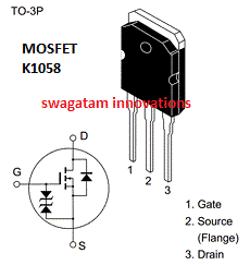
We take the example of two types of N-channel mosfets, the K1058 and the IRFP240 and see how these mosfets can be tested using an ordinary digital multimeter through slightly different procedures.
How to Check N-Channel Mosfets
1) Set the DMM to the diode range.
2) Keep the mosfet on a dry wooden table on its metal tab, with the printed side facing you and leads pointed towards you.
3) With a screwdriver or meter probe, short the gate and drain pins of the mosfet. This will initially keep the internal capacitance of the device completely discharged.
4) Now Touch the meter black probe to source and the red probe to drain of the device.
5)You should see an "open" circuit indication on the meter.
6) Now keeping the black probe touched to the source, lift the red probe from drain and touch it to the gate of the mosfet momentarily, and bring it back to the drain of the mosfet.
7) This time the meter will show a short circuit (sorry, not short-circuit rather "continuity).
The results from the point 5 and 7 confirms that the mosfet is OK.
Repeat this procedure many times for proper confirmation.
For repeating the above procedure each time, you will need to reset the MOSFET by shorting the gate and the drain leads using meter probe as explained earlier.
How to Check P-Channel Mosfets
For P-channel the testing steps will be as per 1,2,3,4 and 5, but the polarities of the meter will change. Here's how to do it.
1) Set the DMM to the diode range.
2) Fix the mosfet on a dry wooden table on its metal tab, with the printed side facing you and leads pointed towards you.
3) With a any conductor or meter probe, short the gate and drain pins of the P-mosfet. This will initially enable the internal capacitance of the device to discharge, which is essential for the testing process.
4) Now Touch the meter RED probe to source and the BLACK probe to drain of the device.
5) You will find an "open" circuit reading on the meter.
6) Next, without moving the RED probe from the source, remove the black probe from drain and touch it to the gate of the mosfet for a second, and bring it back to the drain of the mosfet.
7) This time the meter will show a continuity or a low value on the meter.
That's it, this will confirm your mosfet is alright, and without any problems. Any other form of reading will indicate a faulty mosfet.
If you any further doubts regarding the procedures please feel free to express your thoughts in the comment section.
How to Test an IRF540 Mosfet
The procedures are exactly similar to the above explained N-channel mosfet testing procedures. The following video clip shows and proves how it may be implemented using an ordinary multi-meter.
Practical Video Tutorial
Simple Mosfet Tester Jig Circuit
If you are not convenient with the above mentioned testing procedure using a multimeter, then you can quickly construct the following jig for checking any N channel mosfet efficiently.
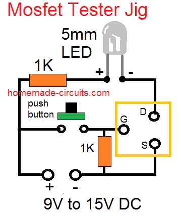
Once you make this jig, you can plug-in the relevant pins of the mosfet into the given G, D, S sockets. After this you just have to press the push button for confirming the mosfet condition.
If the LED glows only on pressing of the button, then your mosfet is fine, any other results will indicate a bad or defective mosfet.
The cathode of the LED will go to the drain side or drain socket.
For p-channel mosfet you could simply modify the design as per the following image




Questions & Answers
This is a useful step-by-step guide, especially for beginners who are trying to distinguish a faulty MOSFET from a good one using only a digital multimeter.
Thanks for your feedback, Glad you found it helpful…
Hello Swagatam,
I just wanted to reach out and say thank you!
Your MOSFET testing jig proved to be very helpful and was very appreciated.
Jerome from Texas
Thank you Jerome! I am supper glad to know you found the above concepts helpful, please keep up the good work!!
Swagatam,
I built your jig today and tested 30 MOSFETS; they are TO3 packaged and are for stereo amplifier outputs. 5 “P” channel and 2 “N” channel devices showed slight glowing of the LED before pressing the button. Pressing the button brought the LED to full brightness. I assume the subject MOSFETS are leaking and should be replaced. What say you? I am experiencing negative rail voltage on the right channel and have tested all the other devices on the board either by replacement or removal and replacement. Thank you, Jack
Thank you Jack,
It could be that the MOSFETs are leaking or maybe the LED is just too sensitive and might be detecting even a leakage in millivolts.
You can try pressing the button without any MOSFET connected, if the LED does not glow then we can assume that the MOSFETs might be leaking slightly. You can also try the same with a BJT and verify the results.
Hello, I often see RF Power transistors such as the MRF454 referred to as a MOSFET, but the data sheet calls them a RF Line NPN Silicon Power Transistor.
My question is can the MRF454 be tested in the same fashion?
If yes, then I would guess that the test circuit you show should work as well.
MRF454 is not a MOSFET, it is a BJT, so it cannot be tested using the methods explained above.
It can be tested just like any other BJT is tested.
Hello dear.two irfp450 are same factory.and ones bipping in multimeter and other is 200 ohm range.are they fine?
If both are showing different test results then one of them could be faulty.
Pls can you help on dspic30f2010 board design
Sorry, I have no information with me about this topic.
Hello Swagatam,
I am troubleshooting a DC-AC power inverter and suspect the MOSFET’s
They are SSF7509 N-type
Have taken out and tested both.
1. Shorted G-S
2. Meter in Diode mode, Red probe-D, Black-S = Nonconductive
3. Red-G, Black-S 4.Red-D, Black-S = Low Reading, but diminishes to nonconductive
Is this Normal?
From what I’ve found and understand is that once charged, D-S will be conductive till G is reset. Is this correct?
If this correct does this mean these MOSFET’s are bad?
Thank you much,
Ken
Thank you for the response.
Yes, I do short to reset and will build the circuit to test.
But, in theory. once the Gate is charged should the Drain to Source remain conductive till the Gate is reset?
Yes, once a Metal-Oxide-Semiconductor Field-Effect Transistor (MOSFET) gate is charged and the FET is turned on, the drain-to-source channel should remain conductive as long as the gate voltage is maintained above the threshold voltage (Vth) required to keep the MOSFET in the “on” state
Thanks Swagatam,
I found another unused MOSFET and tested all with the given circuit and all tested OK. I also metered the unused MOSFET, as before with the other two, yielding the same results and answering my question. The Gate is not like a sliding screen door where the door closed is uncharged and open is charged, remaining open till reset closed.
Rather the Gate is similar to a hinged screen door with a spring dampener. Open the screen door, charged, it will only remain open till the spring closes the door, slowly discharging.
Thank you so much Ken, for your detailed feedback.
Your explanation makes sense, I hope the readers will find the information very useful.
Hello Ken,
As explained in the article, initially the drain and the gate must be shorted together.
If you are not getting results exactly as suggested in the above article, then the MOSFET could be faulty.
Instead of checking the MOSFET with a meter I would recommend using the MOSFET tester circuit as given at the bottom of the article. This Jig circuit will be able to confirm with 100% accuracy whether your MOSFETs are good or bad.
Hi there, I’m a complete newbie, a retired mechanical engineer who’s fed up with always always coming to a dead end whenever something goes wrong with electronics (I play around a lot with off-grid pv setups and have several inverters and mppts that no longer work) so I am trying to teach myself how to diagnose and repair electronics. So I just opened up a non working mppt and attempted to test all the various mosfets (in circuit) but did not get any repeatable results- they were changing almost every time. Is that because I didn’t unsolder them from the pcbs? Do I need to do that if I want to test them? Thanks a lot for your hrlp, in advance!
Paddy Glenny
Yes, you will need to remove the MOSFETs or any other components from the PCB in order to test them correctly.
Thank you very much. Not the answer I was hoping for but very helpful!????????
You are welcome!
What type of transistor IRFP240
It is a 200V, 12 amp N-channel MOSFET
hi
what type of transistor is a G40N60 .is it a mosfet or an igbjt and how do you test an igbjt.it is out of a 12v dc to 240v ac inverter thank you
Hi, It is an IGBT.
I have not yet investigated how to test an IGBT. You can search it online and let us know if you are able to find the procedures.
Sir, Thank you very much for all the time you put in this explanations. Great job.
Question, i test a J599 p-channel and i have a reading after touching the drain BUT it last for half a second. Can i say that the mosfet is ok?
Hi Danny, Sorry, I am not able to confirm that. I think the results should be exactly as explained in the above article…anything else might indicate a doubtful device.
Hi Swagatam,
I see your reaction now. Sorry I sended again. Just delete it.
Thanks for youre reaction. The next step will be ordering the parts and see if it works.
No problem Danny, all the best to you!
Afternoon from here am delighted to say I am ok with the steps used to test mosfets which before now I had no idea it could make a SMPS not to light on a laptop charger which am working on but after reading your review I am really convinced I can work on the charger and get it fixed. Thanks for the reviews and the new ways in testing other components.thanks
It is a great pleasure. Glad it helped!
i am testing an N channel AB package. it will test normal (showing an open circuit on the drain) when using the ohm setting on my DMM but i dont get an open circuit when using diode test. the drain reads .516 before touching red lead on the gate. either way it will then switch and show continuity. does the diode test indicate a bad mosfet since it is not completely open on diode test?
A MOSFEt needs to be tested exactly as explained in the above article, any other form of testing as mentioned by you might not be appropriate and might not show the correct results.
Hello. Can I put both LEDs in the same circuit together but in parallel? I think it should work too.
The JIG connection layouts are different so connecting LEDs in parallel might not help to test both mosfets with a single jig.
Hi,
Can I suggest something? The difference between the 2 images is simply the polarity of the battery connections. In the N channel, the – goes to the Source, while in the P channel, the + goes to source. Hence, you basically only need more wires and a 3P-2C switch to invert the battery connections. Just remember to remove the testing MOSFET before switching.
Am I correct?
Hi,
Along with the supply polarity, the LED polarity also needs to be changed.
How do I distinguish an ordinary transistor from a MOSFET
You can check and distinguish them only through their printed numbers.
Thank you
For a good P channel mosfet does the led will go off when pressing the push button (ie the opposite of the N channel mosfet case) ?
Thanks.
For the P channel Jig also the response will be the same. The LED will illuminate if the mosfet is good. Please note the polarity of the supply input DC and the LED, they are both opposite compared to the N channel Jig
Dear Sir,
Please sir, the glow of the LED. Is it by pressing and holding the push button?
Or just pressing it and releasing the button?
The result I have using the tester is that the bulb glows when pressing and holding the push button, when I release the button the LED is off.
Hi Godfrey,
Your testing procedure is correct and it shows the MOSFET is good.
Circuit for testing is extremlly simple and useful. All my problems solved in half of hour. DMM can’t test high power MOSFET like 2SK2837 but your circuit do the job. Thank you very much.
You are welcome, and glad you found the circuit useful.
Greetings sir,I fine your write very very interesting. I will to learn more about inverters the function and fault tracing. I found the diagram you design for testing p channel MOSFET and N channel very interesting. My appreciation. I like to get to you via email
Thank you Frederick, glad you liked the post!
Sayın Swagatom hocam Merhaba yaptığınız tüm çalışmalarınıza teşekkür ederim. Bizler sizlerin bu bilgi paylaşımlarınız sayesinde kendimizi geliştiriyoruz yukarıda bahsettiğiniz K1058 Mosfet transistörün Gate – Source ayakları arasında iki diyot kullanılmıştır. Bu diyotlar niçin kullanılmış
Bu mosfet transistörün yerine muadil mosfet transistör kullansam devrede çalışır mı. Bende arızalı besleme devresi var burada 26NM60N kullanılmış bunun yerine 26NM60 kullansam çalışır mı? teşekkür ederim.
Hello Turan, Glad you found the article helpful!
Those two diodes are placed internally on the MOSFET package, in order to protect the gate from transients.
Yes any equivalent mosfet will work. 26NM60N and 26NM60 are probably the same, so can be exchanged
Hocam Merhaba cevabınıza çok teşekkür ederim. Kolay gelsin.
You are welcome Turan…
Please sir how to identify the terminal when carry out a test, thanks.
You will have to refer to the datasheet of the mosfet for determining the pinouts
Really narration is too good with very simple English and very simple schematic diagrams too.
I would love to read the articles when ever I face problem in solving circuits.
I am glad the article helped you!
For dual gate MOSFETS, would you do the test twice swapping the gates every time
Yes that’s correct, however dual gate mosfets are very rare nowadays
what is difference between N and P channel test circuit ? It looks same .
supply polarity and the LED polarity are opposite
Ok supply polarity is different in P Channel circuit but LED has no any polarity label. Can you update it please ?
The lower diagram is for p channel, the LED polarity are indicated in this diagram. The upper diagram is for N channel mosfet, the LED pin on the drain side will have negative polarity.
thank u sir for your tips.
Dear sir
Thank you so much for the above simple circuit.Cramming the above 7 steps can be challenging when one needs speedy solution to a circuit problem.I would like you showcase steps for analog testing.most electricians- (electronics) use them.Please is there such a simple circuit for testing inductance and capacitance.I have one inductor i got from scrab which i want to use in a circuit but couldnt find the value on its body.is not here i would have given you what is writen on its body.its a toroid one about 2cm or more in diameter .
Thank you.
Patrick, inductance meter and capacitance meter circuits are already published in this website, please use the search box to find them.
Will the Circuit using the LED work for BJT too?
Yes it will, but it won’t check the hFE
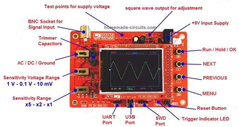
The pic you have shown above is wrong
its shown source as middle pin but its drain instead
you can confirm and thank me.
Which pic are you referring to? The last two pictures indicate the wire connections only, not the pin orientation.
Doing the test on a NPN Mosfet, I have the continuity between source and draing after having charged the gate but this configuration is quickly (within few seconds) going to a open configuration, without touching anything. My understanding is that there is a parasitic resistance that discharge the gate and thus Mosfet is faulty. Could you confirm my understanding ? For notice, my NPN Mosfet has an integrated zener diod protection.
You may be right, because any other result than the explained one indicates a faulty MOSFET, you can further confirm this using the LED jig circuit as shown at the bottom section of the article.
Hello,
We have extend this offer for you to provide us with a price quote for the item listed below:
Extech EX350 Digital Multimeter or Compatible————186 pieces
Payment mode ——————–Net 30
Looking forward to doing business with your company
N.B: This offer for quote is only for USA based companies
Thank you.
Sincerely yours,
Aevolet Gravesd
President, Student Affairs
CITY COLLEGES OF CHICAGO
180 N. Wabash
Chicago, IL 60601
Sorry, presently we are not involved with selling or manufacturing electronic items.
Bonjour
quel est le rôle de diode entre gate et source intégré dans le mosfet?
It’s probably for safeguarding the MOSFET gate from reverse spikes and over voltages.
how I know n or p channel mosfet when it is connected to PCB without looking at ckt?
If the source side gets the positive then it’s a p channel.
First you say short the gate and the drain to reset, then you say short the gate and the source to reset. I know it’s gate and drain just a small typo I’m sure.
Thank you, yes that was a typo, I have corrected it now!
Pls, I’ll like to know if the pin configuration above is same for irf840 and irf1404. Bcos I use your method to test these mosfets bUT they’re not behaving as you said. What do you think am doing wrong. I guess the pins are not in the above order. You can reply through my email if you wish Sir. Thanks.
The pinout of the two mentioned mosfets are the same.
Just now I checked the IRF540 as per the above explained instructions and I could check it perfectly, I will the upload a video soon for everybody.
Sir,
After connecting supply MOSFET has burning how can I check it in microtek hb1125
Rajesh, a mosfet will mostly burn due to a short circuit at the output, connect a fuse in series with the battery to verify the issue…
But I think this article is talking on SO3 MOSFETs,how do I to with SO8 MOSFETs both P & N Channel II meet them on Laptop circuit boards
Thanks,
Amos.
the process will be identical and will need to be done twice for the pair…
I Have Irfp260n giving me read even after I touched the gate is that mean I have to replace it ?
No, it looks OK to me..
I cant have any institute in my country
i need your help to give me some of method to be able to repair any device
you can feel free to ask anything about electronic circuits I will try to sort it out for you.
Sir i want to learn inverter service ,help me to send inverter circuit diagram with service tips
anbarasan, it's not that easy, you'll have to go an institute or a relevant coaching classes to learn it theoretically and practically