Here I have explained how to build a simple LDR based motion detector sensor circuit using ordinary parts such as LDRs and opamps, reasonably accurately.
What are Motion Detectors
Motion detector or sensor alarm is a device which detects the presence of a motion or movement within a certain fixed range and raises an alarm on doing so.
You might find many electronic circuits related to motion sensing but most of them incorporate shadow detection through a single LDR, which does not work very effectively.
Because a shadow might not always be very sharp enough and at times the circuit may just fail to interpret it.
The present motion detector/sensor circuit is also based on similar principles but it detects a motion by differentiating the light level using two LDRs, this makes the system more sensitive and works irrespective of the shadow intensity.
Circuit Operation
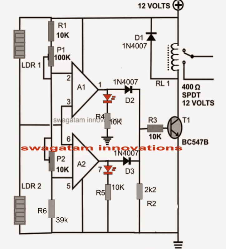
The circuit diagram shows a simple configuration consisting of a couple of opamps from the IC LM324.
The two opamps are arranged in a differential mode and as comparators.
Both the comparators consists of their own discrete light sensing components in the form of LDRs.
The presets provided with the opamps decide at what point the outputs of the both the opamps remain on the same level, that is at zero potential.
Also the above condition is met when the light level over both the LDRs are approximately at the same levels.
However the moment the light level (or the shade level) on the LDRs differ even slightly, the comparators instantly detects this and one of the relevant opamp outputs goes high.
The transistor at the output immediately triggers and activates the relay and the connected alarm mechanism.
The LDRs must be positioned at least a feet apart for proper optimization of the detection level.
Also the LDRs and the nit itself must be positioned in such a way that the ambient light directly become incident over the sensors.
How to Set Up the Circuit.
You will require a lot of dexterity for setting up the circuit accurately. It may be done as follows:
Let a constant source of light fall on the LDRs with uniform intensity.
Now without letting any of your body part disturbing the light source, gently and skilfully adjust the two presets such that both the LEDs just shut off.
That's it, your circuit is now all set and ready to detect even the slightest of motions across any of the LDRs.
However it must be ensured that the light source intensities on the LDRs does not change, or else the set up could get rattled.


Questions & Answers
sir, what is range of that of that product
It will work as long as shadow is reachable on the LDRs…
Hi Sir!
Does this circuit works even without the inductor??
there was a missing resistor (R6) in the circuit which was creating all the problems, it has now been put into place, please take a note of it.
I indeed regret the mistake a lot.
Sir, Leds are glowing fully and are not turning off by rotating the pots when pots are connected same as in circuit diagram..
But when i reconnected the poted in another way as you told ABDUL BASIT It also gives no result. Plzz help meee
there was a missing resistor (R6) in the circuit which was creating all the problems, it has now been put into place, please take a note of it.
I indeed regret the mistake a lot.
note: pin3 and 6 of the IC are not linked with the presets….
Prince, if you have built it exactly as shown in the circuit then definitely it should produce the intended results.
Check the circuit connections and polarities there could be something wrong with them.
Follow the setting instructions very carefully and do it exactly as it's mentioned.
Sir please evaluate the circuit completely and the value of the ldr sensors
I used 12v ac to dc charger as it has positive charge inside the pin and negative charge outside the pin. As i give negative charge to positive terminal the circuit works. But when i connect positive terminal to positive charge it does not works .
Plzzz guide me
Prince,I could not understand your problem, the above circuit has all the details you need.
LDRs should have around 10k to 50k resistance when exposed to ambient light, check this without connecting them to the circuit.
Check the output of your adapter/charger with a meter and then connet the terminals as per the polarity shown in the diagram.
sir circuit is working now but transister is not triggering .so alarm does not working.
what should i do????
there was a missing resistor (R6) in the circuit which was creating all the problems, it has now been put into place, please take a note of it.
I indeed regret the mistake a lot.
If you connect everything correctly as shown in the diagram the transistor and the relay will surely function. check transistor polarity, relay diode polarity, transistor base voltage etc.
SIR NOW CIRCUIT IS WORKING OPPOSITE.WHEN LDR'S DETECT LIGHT IT STARTS ALARM AND VICE VERSA.
Connect LEDs as shown in the diagram to see the response….
sir problem is coming that only led corresponding to A1 IS GLOWING.. LED 2 IS NOT WORKING..
OK SIR… I WILL DO THAT CHANGING & INFORM YOU
replace P2 with a 4.7k fixed resistor and then check by varying P1.
THANKS SIRR ..
MY PROJECT IS READY ONLY BECAUSE OF ""YOU"".THANKS SIR.
SIR I WANT TO INCREASE ITS SENSITIVITY, WHAT SHOULD I DO BECAUSE ITS SENSITIVITY IS LOW. IWANT TO ENHANCE IT
you are welcome Abdul,
actually the circuit is very sensitive, but unless & until some kind of shadow falls on any of the LDRs the circuit won't sense….so it's important for the object to block some light at least, for making the circuit sense it….use slightly powerful lights or place the LDRs wide apart to make it more responsive.
SIR WHAT ARE THE VALUES OF P1 & P2 FOR SETTING UP????
AND SIR TELL ME ARE ALL POTENTIOMETER'S LEGS CONNECTED?
IF YES SIR , THEN HOW THEY ARE CONNECTED??
You will have to adjust P1 and P2 such that both LED stay shut-off. Read the set up procedure given above.
Only the center and any outer terminal is used, the remaining third is not used. for example connect R1 to center terminal of P1, then connect any one of the outer terminal of P1 to ceter terminal of P2, finally connect any one of the outer terminals of P2 with ground and pin5 of A2
Relay will NOT switch OFF as long as any of the outputs are high, both should be completely off for making the relay off.
Anyway, I have present a modified output relay stage in the above article which you can integrate with the top circuit.
With this circuit you won't need to adjust the presets too much, the relay will operate as soon as a movement is detected.
In the given circuit DO NOT connect LEDs at the outputs of A1/A2, connect the 0.22u ends directly with A1/A2 outputs. You can connect an LED parallel to the relay coil with a series 1K resistor.
Good day,
The above design is a simpler option, but you can find many other more accurate ones on the net which are a bit more complex, though.
The above circuit would cost around $2 without the power supply.
Adjust it very carefully so that both the LEDs remain switched OFF under the given light conditions.
Make sure your shadow or any other interruption does not come across the light source.
If possible I'll try to modify the circuit with a different output parameter so that the above difficult setting can be avoided.
A1 and A2 are positioned as voltage comparators which trigger as per the resistances of the LDRs, you can Google how 741 comparators work to learn more.
A1 pins are same as 741, for A2 pin6 is pin2 of 741, and pin5 is pin3 of 741.
The above circuit does not require an LED ight, the normal house light or a night lamp will be enough to keep the circuit in detection mode, when somebody comes in between one of the LDRs and the light, the output will trigger.
It was built long time ago, the prototype was dismantled for a different project so cannot provide the pictures.
P1 should be a preset, while P2 can be a pot for fine adjustments.
The above adjustments should be such that the output LEDs and the relay stay shut off under the specified light or illumination conditions over the LDRs
The angle or the position of the illumination over the LDR must not change once the adjustments are done.
The position of the LDRs is not critical but should be at least a foot apart which again must not be changed once the presets and the pot are adjusted as explained above.
yes that's correct.
You can replace AC suply with the existing 12V DC, if the alarm is a DC operated unit.
12V is connected with the relay coil (the square box),
N/C (the upper contact) is open, not connected to anything.
N/O(the lower contact) and the central pole goes to the load which needs to be activated such as an alarm etc. via the AC supply.
Please click the above diagram to enlarge, you will see a clearer and a much bigger diaram
yes 741 can be used here.