Triacs are one of the most important active electronic components which are exclusively used for power switching applications, these devices are especially suited to AC mains loads, and are able to switch large currents consistently.
Triacs are the solid state replacements to mechanical relays, and come configured as static relays.
The modern triacs today are highly sophisticated with their specifications and make, one such example is the BTA41, 600B, I have explained its technical specification and datasheet from the following points:
Identifying Print Value of BTA41/600B
- BT indicates series number,
- "A" represents that the device is insulated, while B would mean non-insulated. The insulation is provided on the Tab of the device upto 2500 volts.
- 41 = 4 and "one" zero, that equals 40 Amps
- 600 is the voltage handling capacity, therefore here it's 600 volts.
- B represents the triggering sensitivity that's 50mA in this case
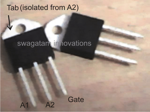
- Absolute Maximum Rating (at around 25 to 40 degrees Celsius)
- RMS, continuous current handling capacity = 40 Amps
- Non repetitive peak current = 400 Amp, only for max 20ms.
How to Connect
The pinouts are connected just as we connect other normal triacs. I have explained them yet again:
A1 should be always connected to ground. The ground doesn't have to be necessarily the neutral of the AC, it can be any one wire out of the two mains input.
The other wire will go to one of the load terminals, while the second wire of the load will go to A2 of the triac.
The gate should be connected with the desired trigger input which must be a DC, because the triac will conduct with every rising positive edge of the DC trigger.
Here the minimum triggering gate current is 50 mA.
A1 should be made common with one of the AC terminals as well as the ground of the DC trigger circuit, in case an external triggering circuit is incorporated.
Application Notes
As suggested in the above sections, the triac BTA41/600B is best suitable for applications concerning control of AC loads such heater coils, high power halogen lamps, AC motor pumps or simply motors such as in dryers, blowers and so forth.
The following circuit illustrates how the device may be utilized for controlling heater coils such as in furnaces, induction cookers etc.
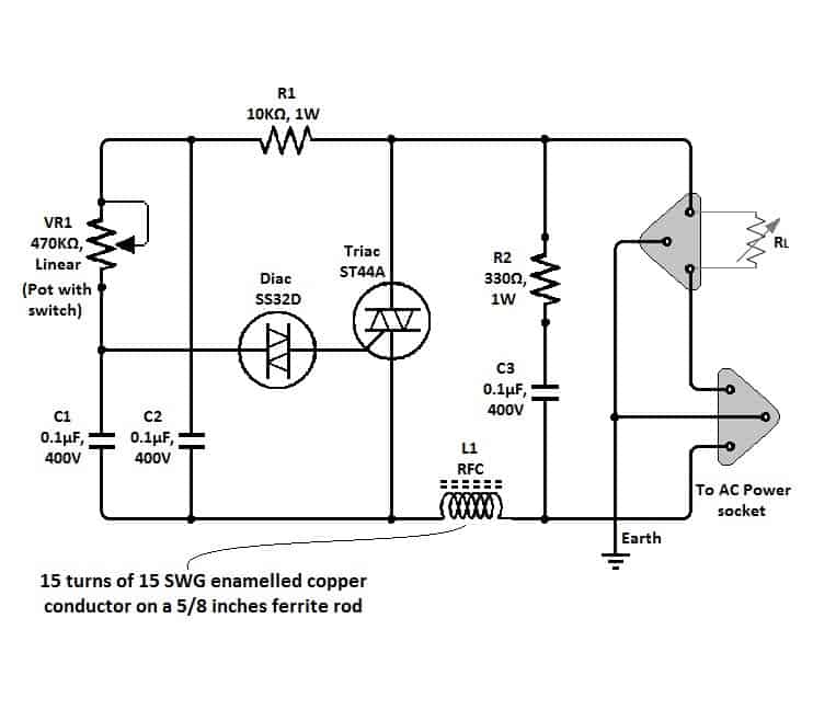
The above circuit can also be used for controlling AC motor speeds simply by replacing the heater coil with the motor wires.
The adjoining diagram depicts another application of BTA41/600 where it has been configured as a PWM assisted AC motor controller or even heater coils.
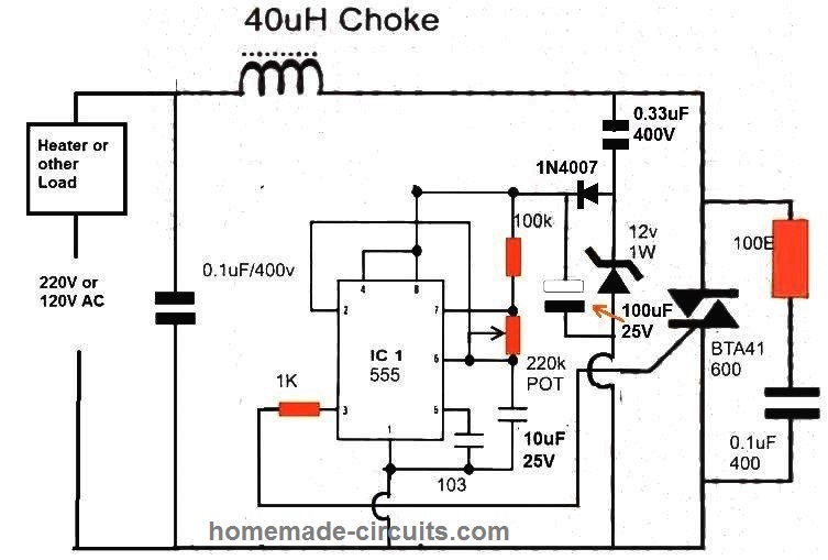
WARNING: The above circuits are not isolated from mains AC, and therefore are extremely dangerous to touch in open and powered condition.


Questions & Answers
Hello sir. Can I make without inductor. I mean only triac, diac, capacitor, resistor. Potentiometer.
Hi Sakib,
yes you can skip the 40uH coil and the left side 0.1uF capacitor, and still get the intended results, however without the LC network, the circuit will generate a lot of RF noise and interference on nearby AM radios.
Hi Swagatam,
I would like to use the second with 555 timer for making a soft starter for my submersible pump (1.5 – 2 Kw) for a community farm. Is it possible. What I do want is using a MCB to switch on then the load will be fully started after 1-5 seconds longer or more to reach full speed or power.
Changing the value of the potentiometer will make the ramping up time longer? Also the Choke, do I have to use this choke?
Please advise
Best.
Hi Dang,
Yes that’s possible. But the controlling will need to be done manually.
Meaning, initially you will have to adjust the pot at narrow PWM level and then once the load is switch ON, you can increase the PWM to maximum.
However, if you want to have this soft start fully automated then you just have to connect a 100uF capacitor between pin#5 of the 555 IC and the ground.
Hi Swagatam,
Thanks for your response. My scenario is:
MCU control the MCB with an internal small relay (to supply AC power to the coil of the MCB for it to start)One the MCB starts, the board will automatic handle the soft starting for the pump in xx seconds.So with your advise, adding a capacitor to pin 5 of the 555 to GND, it will automate the soft starting in xx seconds using the set level in the POT? In your schematic, there is already a 103 Capacitor connecting ground. From your schematic, i understood that Live and Neutral are non interchangeable! Can you advise a value for the POT to make the 10 seconds ramping up to full power?
Many thanks for your advise
Best,
Hi Dang,
Here are answers to your questions.
You can replace the 103 capacitor at pin#5 with a 100uF or a 220uF as per the desired length of the slow start.
In this situation the pot can be used to set the maximum range of the pump speed. According to me the pot must be removed and replaced with a fixed resistor so that a maximum speed can be set using the two resistors.
The ramping length can be directly set through the capacitor at pin#5.
Make sure to test the results using an oscilloscope first.
Preferably, the phase or the LIVE should be connected to the LOAD side terminal, but this is not mandatory.
Even if you reverse the L/N connections the circuit will still keep functioning normally.
Hi – I would like to use the PWM assisted AC motor controller circuit to replace the triac driver in a large carpenters plane. The present triac driver circuit is not working. What frequency range and pulse width should I consider configuring the 555 for? The 10uf cap appears to be too large for a motor driver application, as the frequency is in the 1Hz range. What should the gate drive signal look like relative to the 60 Hz line frequency? Thanks in advance for your insight.
Hi, you can try reducing the capacitor value to 0.47uF and see how it responds.
The 60 HZ would be allowed for a few milliseconds by the PWM ON cycles and then interrupted by the PWM OFF cycles.
I would also suggest you to try the first circuit which is ideally suited for controlling AC motor speeds.
Hi Swagatam
I would like to make my own version of a solar proportional immersion heater controller to use surplus electricity from my solar PV array. I assume that an appropriate circuit will use this triac which will be triggered by a current transformer on the supply to the property to provide enough load to bring down the export of electricity to zero – tested during each cycle.
I would love to make a trial version but don’t have a circuit diagram – can i use this circuit and how do i integrate the current transformer?
Thanks
Gordon Webb
Hi Gordon,
I have current transformer circuit in this blog which can be perhaps modified to suit your application.
You can try the second schematic with a buzzer. If it works with a buzzer then a triac could be used at the output to switch ON a desired load.
https://www.homemade-circuits.com/load-current-control-through-current-sensing-transformer/
Hello, I have made this circuit with 555 pwm and trying to run infrared cooker coil with triac BTA41600B. But i am getting huge ac voltage on gate and gave 1k resistance to 555 pin3 to gate and resistance just burnt.none of triac pin is sorted.Is it okey to gate high voltage in gate?three of my 555 ic is already damaged.
Hi, How is it possible to get a huge voltage at the triac gate when the 12V zener is connected?
Did you connect the 0.33uF capacitor and the 12V zener diode?
You can try using 0.22uF instead of 0.33uF and check the results.
The voltage between pin8 and pin1 of the IC should be 12V, and the same should appear across the gate and the ground of the triac.
would you have a economical power supply circuit for a diy wire edm machine
Please provide more details for the power supply.
Hello Sir, I needed a Speed Controller for Industrial DC Motors.
Is it possible to use Your above circuit with combination of a MB3510 bridge rectifier for the
DC Motor? and also what modifications i can do to above circuits for using 2 phases as input of 440V AC to feed the bridge rectifier MB3510 and later the DC output to the motor?
I have posted the more detailed message on facebook with both the motor plates, Please Kindly Check, Waiting for Your Positive Reply
Thanks 🙂
Hello AK, for operating a DC motor you can try the following circuit:
More details are provided in the following article:
https://www.homemade-circuits.com/dc-motor-speed-controller-circuits/
Thank You very much for replying Sir, but Sir one of my DC Motor eats Four Hundred & Fourty DC Volts @ Ten point One Amperes of Current, and the another small one eats Two Hindred & Thirty DC Volts @ 8.1Amperes, how can such small circuit going to handle that much high load? and also can i by doing som adjustment i can control the speed while maintaning the torque with a external 0-10Volts DC supply?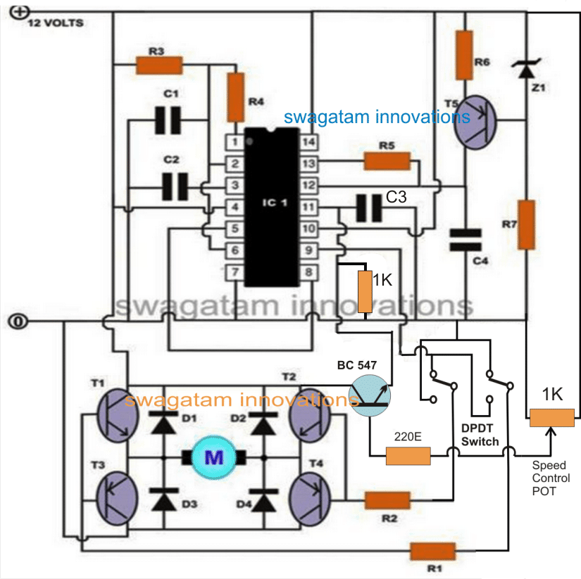 )
)
I messaged on Facebook with much details earlier where You suggested me this circuit.
(
Waiting for Your Positive Reply . . . .
Thanks
Hello AK, I actually suggested you the following circuit:
You can see that the power transistors have a separate voltage connection for feeding the motor. You can feed the 440 V to the transistors separately for controlling the motor. For this you just have to replace the transistors with appropriately rated MOSFETs.
For further discussions please comment under the following article:
https://www.homemade-circuits.com/dc-motor-speed-controller-circuits/
Good!
Thanks for good job. Can the power booster you made with this triac be used for electronic appliances, such as ac television and radio, also?
Thank you, no, the booster circuit cannot be used for powering electronic devices.
Please, can you help me, then, with a power booster circuit that can power AC electronics. I will be very grateful if you do.
Thank you very much sir.
The only way to achieve this is to build an auto-transformer or buy one auto-transformer which will allow you to adjust the output voltage to the desired levels. By the way, power cannot be boosted…only voltage can be boosted.
Hello, I am looking for a circuit to control 120 A/C volts max 10 amps motor speed aiming to keep as much torque es possible.
The AC motor is to power a spindle of a home made flight cutter for metals such as on a milling machine.
Will that circuit above do?
I
Hi, yes, you can use the above circuits for controlling the specified load. However, decreasing the speed might also cause the torque to reduce proportionately.
Hi Swag, I am repairing this Samson SX3200 amp. It has two bridge rectifiers in each channel circuit. What is bothering me is the function of the negative and positive step driver circuits. Any idea? My email address is cgachuhi@yahoo.com.
Hi Gash, The two rectifiers could be for supplying the +/- dual voltages to the amplifier circuit, because most power amplifiers require a dual voltage to operate. This is my guess, not entirely sure though.
Sir,
My name is Dr.Chris Halgryn and I am a great fan of all your circuits however Sir, the circuit I want to build now looks good it is the speed controller using a BTA41 connected in series with a 0.1uF cap…. but, at the end of the schematic it shows a device marked “100E” what is this please????
Thank you
Chris
Thank you Dr. Chris,
I am glad to help you!
100E = 100 Ohms
the letter E stands for Ohms.
Thank you Sir my goodness I at first thought it was OHMS yet I feel such a fool but Thank you again for the prompt reply I keep on following your projects, built a few all in the past….. and YES!!! They all work fine thus, everybody should be thankful for ypour projects and schematics thank you again I HIGHLY Recommend you!!!!
Thank you
Dr.Chris
PS. I need a circuit in order to control the speed of my UNIVERSAL MOTOR without LOOSING TORQUE can you assist or will the present circuit help me… please thank you in advance~~
No problem Dr. Chris, I am always happy to help! I am also glad to know that you have tried my circuits and they worked for you, appreciate your kind response!
I have a high torque motor speed controller circuit published in this blog, but the circuit can control only low current motors up to 3 amps:
https://www.homemade-circuits.com/constant-torque-dc-motor-speed-controller-circuit/
Hi….I want to make a 3-phase voltage regulator to control the voltage input of a transformer’s primary winding, so that the output voltage of the secondary winding can be adjusted. The current requirements for the primary is max 20 A per phase. Can you help me with a suitable schematic ? I am planning to make use of 3 nos. of standard single phase SCR (BTA41 600B) voltage regulators connected in a star configuration (220V INPUT) and will take the outputs of these in a delta configuration (400V OUTPUT) to the transformer’s primary. Any suggestions will be a nice gesture…. thanks
Hi, sorry. I can’t figure out how a 3 phase AC regulator can be built. It seems difficult because there’s no neutral in a 3 phase system. If there was a neutral we could have simply used 3 AC light dimmers on each phase for controlling each of the phases.
Hi Swagatam….Of course there is a neutral in the three phase system, and that’s why in the absence of a single unit of 3-phase transformer, we can connect 3 units of single phase transformers for 3 phase use. The method is known as STAR-CONNECTION. The output can be made available as a no-neutral setup (called as a DELTA CONNECTION) or otherwise.
I actually wanted a good high power (standard single phase) dimmer circuit design with symmetrical wave-forms at the gate. And I will actually use three of them for the three phases, take each one’s phase output and use them as I wish, meaning STAR (with neutral) or DELTA (without neutral).
Thank you Aditya, for the information!
After some thinking I realized that for connecting a light dimmer on each phase a neural connection may not be required since light dimmers are designed to work in series with the load. So I think you can use 3 good quality high power light dimmers and fix them in series with a DELTA 3 phase wiring.
I have a light dimmer related article which you can find in the following link. The circuit shown under “Circuit Diagram of an Improved Light Dimmer” is a good circuit which was originally designed by the elektor-electronics engineers. However, to get a symmetrical control from the 3 dimmers you may have to use a ganged potentiometer for the 3 dimmers.
https://www.homemade-circuits.com/how-to-make-simplest-triac-flasher/
Hi, I’m intending to use a BTA 41-600B pot controlled regulator circuit (common on ebay etc advertised as a 220v 4000w regulator) to power an old valve radio main circuit (separate 6.3v tube heater supply) in place of a failed transformer. I will be connecting the output of the regulator to a silicon bridge rectifier which then feeds the radios circuits. As the regulator needs to be load connected to make it regulate will the rectifier alone be enough to trigger regulation. Otherwise I was going to build a small filament lamp into the case to fire up the regulator when switching the radio on. Not to sure what current draw will be needed to make the regulator start regulating.
Thanks in advance.
Hi, using a triac dimmer with mains AC can be risky for any low voltage project, therefore I would recommend you to go for a transformer and not with a triac based power supply.
What is the best testing method for a Triac p/n BTA41600B, outside of the circuit.
Thank you
Hi, the inductance should 40 uH. The 15 turns is probably incorrect, it must be around 50 turns
The core should be a ferrite core, If you use air core then the number of turns will increase significantly.
a 2mm diameter wire should be quite enough for handling 25 amp current.
Thanks for replying, can
the ferrite core (due to poor repelability) be smaller than 5/8 of an inch?
If so, would there be problems using this coil for 25A?
Thank you
You are welcome, It may be difficult to provide the exact size of the ferrite core. You may have to find it with some trial and error to figure which core and number of turns produce minimum RF disturbance on radio
Hello sir swagatam, thanks for your electronic guidiance.I’m nosa,I have a question,is it possible to use 3kva alternator generator ac output using BTA41/600b and to power 3hp ac electric motor or higher electric motor and can it runs the ac motor continuously without damages to the BTA41/600b circuits or what kind of circuit will you recommend sir.
Hello Nosa,
since the triac is rated to handle 40 amp continuous current, it should be able to handle the 3 hp load easily. So you can try it. Just make sure to mount the triac over a large heatsink
Thanks sir,I sent you an email of the picture of such design generator I want to use the triac circuit on.
I guess dis is your email address: hitman2008@live.in.
Here is my email address: nosaglee@yahoo.com. to send me usefull information sir.
You are welcome Nosa, however, I prefer discussing only through comments so that it can be read by all of us.
Yes you can use a BTA41 triac since it is rated to handle 40 amp current, meaning 220 x 40 = 8800 watts provided i mounted on a large heatsink
OK sir,from the above diagram of bta41/600b triac,so which side to connect the triggering DC to triac diagram or how can I connect the DC 5v or 12v triggering to the same circuit with the AC bta41/600b.please sir indicate to me the place in the diagram.
Nosa, you can refer to the first diagram from the following article, which suggests exactly how a triac needs to be configured with a DC switching circuit and an AC load:
https://www.homemade-circuits.com/simple-triac-triggering-circuits-explained/
Hi Swagatam,

I like to replace the BT136 by BTA41 due to fail, cause of overload. Here BT136 triggered by a resistor, not a diac, does BTA41 work on this circuit?
Thanks.
Hi Awak, if your bT136 is working with a resistor gate triggering then a BTA41 will also work, but you may have to reduce the value of the R1/R2, because BTA41 needs a minimum 50 ma to get triggered.
Thank for response.This R1/R2, meaning reduce both R1 & R2 or either R1/R2?
Regards.
Try with the existing set up first, if it doesn’t work properly then you can decrease the value of R2 a bit, if it still doesn’t work properly then finally you can reduce the value of R1 and check the response
Ok thanks, I will try.
Thanks for suggestion. Any Iink please for optocoupler driver?
After referring to your previous diagram I could not figure out how the opto coupler could be connected, so cannot go ahead with it. You can try using a 100uF in place of the 47uF and see whether it solves the problem or not. Try increasing the 47uF value and lowering the R2 value, until the right combination is found.
It seems along with R2, C2 is also responsible for delivering the required amount of current to the triac gate
As we know transistor can double the power by parallel, any suggestion if this BT136 I make it parallel to bear the excessive?
Unfortunately, it is not possible to connect triacs in parallel, instead you can try adding an opto coupler driver in place of the BT136, and then drive the bigger triac BTA41
Already reduce bit by bit, reducing one cicle R2 & then decrease R1 and so forth till both reach 5.6ohm, but the TRIAC does not run. Please advise. Thanks.
It is now difficult to understand, because if BT136 is working then BTA41 should also work, it is just about providing sufficient gate current to the BTA41.
BTA41 just requires 50 mA to run, and 5.6 ohm is too low, it doesn’t need to be that low for driving the BTA41 triac. Can’t troubleshoot it at this moment.
Already try to reduce R1 to 20K, not triggered; then R2 to 1.2K, not triggered; then again R1 to 18K, not triggered. Any idea what proper value for R1 & R2 so that BTA triggered? FYI, existing set up already run for soft starting my home water pump, but unfortunately it last only for 2 days & then fail. Try replaced the BT136 with same one, same, just last for 2 days. Please help
Thanks.
Keep reducing the gate resistor further step by step, it will surely work, considering the fact that it worked with a BT136, so it has to work with a BTA41 also.
I think there are lots of detailed explanations you always offer in your tutorials.
Thanks.
However, let me ask,
I used MOC3020 to fire ON/OFF BTA41-600B. the first time I switched on, the limiting resistor in series with the current into the MOC3020 burnt immediately. I used 1K.
Can you suggest better value?
I am driving A.C MOTOR 1000W.
Thank you, where did you use this 1K, at the input side or the output side? I guess it is on the input LED side of the optocoupler. If it on the input side then it very strange, because the input side has no connection with the load side. You can try 4k7 and see if that helps!
Hi Swagatam,
Thank you for the article. I learn something new today. However, I have case and wonder if you could help. I bought a spot welder control module from Amazon. The module can also be seen on aliexpress.com. The issue is every time, I hit the trigger, my circuit breaker tripped. The module uses the “BTA100-800b” . I wonder if I could use the chip BTA41/600B to resolve this issue. My home panel is 100A max. Each breaker is 15A or 10A. Thank you very much.
Hi Dylan, The tripping is happening due to over current drawn by the welding output load. BTA100 is just a switch which is rated according to the load current, so the 100 indicates its maximum tolerable current limit which is 100, which also means that a BTA41 will handle only 41 amps. So if you replace the 100 with 41, it may quickly burn due to the excess current above its tolerance limit.
If you think the welding machine is correctly producing the 100 amp for a 100 amp output load, in that case you may have to upgrade the tripping limit of the controller from 10A to 100A or as suitable, instead of replacing the triac.
Hi Swag,
What is the consequence if I don’t use choke?
Hi Edyrakh, the circuit will still work, but will generate a lot of RF noise in the atmosphere which may create disturbance in radios or other wireless equipment.
Can I use the circuit for higher current of triac like BTA100-800b?
I need to control temperature of various length of nikelin strip that I use to cut artificial fur. Curently I use autotransformator. The voltage that I use between 5V to 70V with maximum current of 30A.
you can do it but if your load is rated at 70V then it can be risky to use this circuit with 220V input, because the 300 peak voltage from the AC can damage your load. You can use the above circuit for controlling 220V load
Hi Swagatam,
I am trying to get calculation for correct value of resistor for triac. As you guided above, look at datasheet and gate current Vgt (12V), Igt (50mA) >> R= 240 Ohm. I also found another person talking about this using the Peak current and R for the gate is calculated by R= V*SQRT(2)/Ipk = 220*SQRT(2)/8Amp=38.8 Ohm.
Actually, I will use your approach, however, the provided guideline is here (for minimum value of Ohm for gate resistor)
https://www.onsemi.com/pub/Collateral/AN-3003.pdf.pdf
Apply for the case of BTA 12, I did not see the parameter for Vg but the test sheet with applied Vg 12 (Max) Ig 50mA and this make me a bit confuse on how to calculate the required resistor value for gate.
Please take a bit of time to show me.
Using your guidance, I found the safe ohm value should be 240 Ohm also.
Thank you very much for your attention.
From Vietnam
Hi Dang, yes it is definitely not dependent on the Vg parameter, rather solely on the IGT which is the triggering current for the specific triac at a given ambient temperature.
I have discussed the subject elaborately in the following article, which you can refer below, to get a simpler idea regarding how to select the gate resistor for any triac….just by using Ohm’s law
https://www.homemade-circuits.com/triac-circuits-working-and-application/
Hi, I’m interested in building a SSFR (Solid-state fan regulator) for old model ceiling fans. I thought of using BTA41/600B instead of BT136/BT137. As BT136/BT137 gets damaged in circuit mentioned at url https://www.homemade-circuits.com/how-to-make-simplest-triac-flasher/ Please suggest suitable changes to be made in your above circuit mentioned in the url https://www.homemade-circuits.com/how-to-make-simplest-triac-flasher/.
Thanks
Hi, BT136 is also a good triac and will not blow if the load is around 200 watts and the triac is mounted on a heatsink.
BTA41 can be used for 1kv and above loads with a heatsink. No changes in the circuit would be required for this.
Hello sir swagatam,av been thinking of including a triac in my Inverter charger to control charging currents since my Inverter uses mosfets body diodes for charging and mosfets doesn’t have current control capabilities,are my thoughts right? And if so then suggest for me the best triac that can control charge current to my batteries. Av got 2 batteries rated 12/200Ah connected in series but am planning to add the batteries as time goes by. So any triac u suggest to me should be able to handle high current even if the batteries are increased. Also I’ll really appreciate if you help with aid of a diagram, thanks in advance.
Hello Evans, triacs cannot be used for controlling current with DC supplies, since they will latch permanently ON when triggered, and will not switched OfF until the supply source is switched OFF
Thanks for the concept sir,the values not given any help?
for 12V battery the zener can be 3V, and the zener resistor can be 1k. The zener value becomes the Vref, which is shown in the formula for calculating the value of Rs. The value of I will depend on the desired maximum current limit
Oh,got you sir. Do you have any in mind that I can use to control charging current in my Inverter?
Good day sir, please I want the full article for the diagram on MOSFET over current control.thanks
Seun, the explanation is very basic. When current exceeds the set threshold, the voltage across the resistor Rs at the + input of the op amp surpasses the reference level at – pin of the opamp, causing the op amp output to become high, which grounds the MOSFET gates via the BjT shutting them off
Evans, current control is supposed to be implemented using the shutdown feature in the oscillator IC, if it is provided in it. If not then you can try the following concept:
Swagatam,
Any suggestions on how to connect the Triac to a high current load. If there is a 4 sq mm wire for 25-30A AC what is a recommendation on how to connect the Triac to that.
Anshuman, If you are referring to the circuit shown in the above article, then it has to be connected where the heater is shown, while also ensuring that the associated cables are rated accordingly.
hi Swag
I really learned alot from your tutorials.
i wish to ask about BTA41, can it be driven by A.C just like others triacs?
i mean, trigger it using MOC3033 (A.C).
i asked because you said it must be trigger by D.C.
Thank you Avong, Triac Gate pin always work with a DC, while the MT1, MT2 pins work with AC. MOC also delivers a Dc to the gate of the external triac.
Sir,
thanks for share your knowledge. I have a question about the right side of the circuit,what is the function of the resistor (100 ohms) and of the capacitor (0.1 uF, 630V). I am especially refering to the difference with the similar circuit: (secod scheme of https://www.homemade-circuits.com/how-to-make-simplest-triac-flasher/).
Thanks in advance
Stefano
Stefano, it is called snubber network, which helps to safeguard the triac from high current spikes, especially when an inductive load is used.
However nowadays most triacs have this feature in built.
Sir pls I need booster for iron
Try the second circuit from this article
https://www.homemade-circuits.com/generatoralternator-ac-voltage-booster/
Thanks sir for your kind reply for using ac load for triac I have powering the timer 555 with the 5 volts want to flash 60watt bulb through triac but its burning the resistor which is placed at output of 555 timer which is 3 pin out of timer please sir you have also not answer about driving thread mill dc motor 180volt 10amp driver ckt thanks
THe pin#3 resistor must be at least 1 K rated. Please use a 1K resistor and connect the triac with the correct pinouts, and make sure the MT2 of the triac has a common connection with the IC 555 ground line.
I have already given you the link for the 180V driver circuit in your previous comment.
Thanks sir I have used 1 kilo ohm for the triac bt137 but still the square wave coming from the timer is stopping at one end of resistor help me this my project of triggering gate of triac using timer I have already used relay which is working can you please show me the calculation of gate triggering resistor for any DC supply thanks once again
Hamid, the triac gate resistor is not so critical, any value between 330 ohm and 2k2 should work. make sure you have connected the triac pinouts correctly. center pin will go to the lamp, right side pin is the gate, and the left side pin will go the lamp
Sir i have a question regarding the 555 timer output can the pin 3 of timer can be given to the gate of the triac bt 137 bt 136 in order to achieve flashing the 220 volts 60 watt bulbs a resistive load if so what are the voltage should i used to power up the timer its either 5 volts or higher what current should i used what should be the resistor value should i used to limit the gate triggering current and voltage can i use opto isolator also called as opto coupler Today i have used the 555 basic alternating flashing ckt i have constructed on veroboard i have given the the output to the triac bt137 which is having 50ma of gate triggering current but some how the ckt is not working the leds are flashing but the gare of traic is not triggering please give me proper guide lines how to trigger triac easily in experiment i have used 330ohm quarter watt resistor which indeed not working what should be the resistor value for triggering bt137 Waiting for your reply
Hamid, for the IC 555 timer you can use 12V DC. Triac cannot be ud for DC load such as LED, that is why your triac is not working. for triggering the triac a 1K resistor will be OK, but the load and its supply should be AC not DC
Thanks
Thanks for your reply