Triacs are one of the most important active electronic components which are exclusively used for power switching applications, these devices are especially suited to AC mains loads, and are able to switch large currents consistently.
Triacs are the solid state replacements to mechanical relays, and come configured as static relays.
The modern triacs today are highly sophisticated with their specifications and make, one such example is the BTA41, 600B, I have explained its technical specification and datasheet from the following points:
Identifying Print Value of BTA41/600B
- BT indicates series number,
- "A" represents that the device is insulated, while B would mean non-insulated. The insulation is provided on the Tab of the device upto 2500 volts.
- 41 = 4 and "one" zero, that equals 40 Amps
- 600 is the voltage handling capacity, therefore here it's 600 volts.
- B represents the triggering sensitivity that's 50mA in this case
- Absolute Maximum Rating (at around 25 to 40 degrees Celsius)
- RMS, continuous current handling capacity = 40 Amps
- Non repetitive peak current = 400 Amp, only for max 20ms.
How to Connect
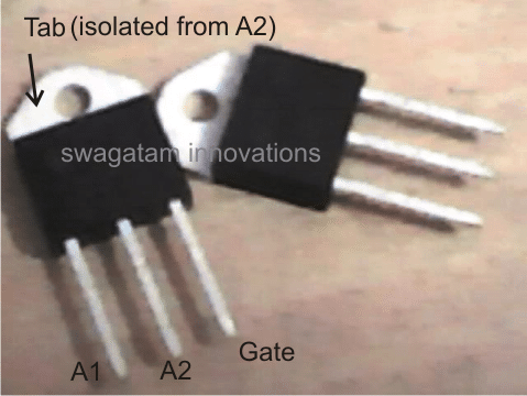
The pinouts are connected just as we connect other normal triacs. I have explained them yet again:
A1 should be always connected to ground. The ground doesn't have to be necessarily the neutral of the AC, it can be any one wire out of the two mains input.
The other wire will go to one of the load terminals, while the second wire of the load will go to A2 of the triac.
The gate should be connected with the desired trigger input which must be a DC, because the triac will conduct with every rising positive edge of the DC trigger.
Here the minimum triggering gate current is 50 mA.
A1 should be made common with one of the AC terminals as well as the ground of the DC trigger circuit, in case an external triggering circuit is incorporated.
Application Notes
As suggested in the above sections, the triac BTA41/600B is best suitable for applications concerning control of AC loads such heater coils, high power halogen lamps, AC motor pumps or simply motors such as in dryers, blowers and so forth.
The following circuit illustrates how the device may be utilized for controlling heater coils such as in furnaces, induction cookers etc.
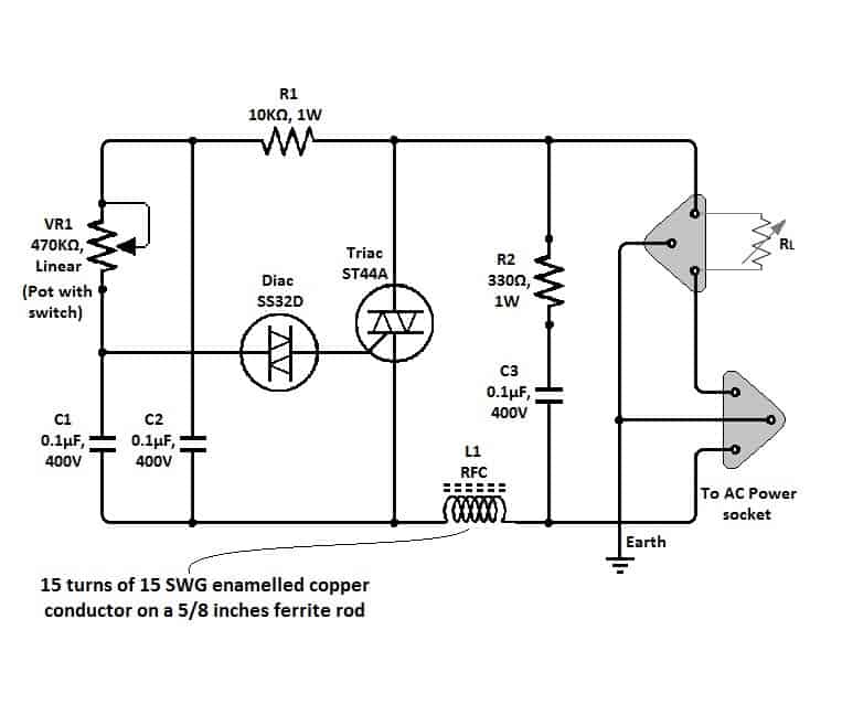
The above circuit can also be used for controlling AC motor speeds simply by replacing the heater coil with the motor wires.
The adjoining diagram depicts another application of BTA41/600 where it has been configured as a PWM assisted AC motor controller or even heater coils.
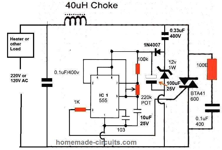
WARNING: The above circuits are not isolated from mains AC, and therefore are extremely dangerous to touch in open and powered condition.


Questions & Answers
Hi, I'm interested in building a SSR (Solid-state relay) for use with Arduino, I thought of this uitllizar BTA41/600B
I have a circuit [api10.net/rele_diagrama.jpg] (if you can access and view, thank you). I'm using a MOC3021.
My question is: This circuit the way it is, it is safe to 40A?
Thank You
Yes it is safe, but will require good heatsinking and at least 50mA of gate current.
Salvador, Bahia, Brasil 24.08.2013.
Swagatam Majumdar
Como faço para modificar os circuitos do BTA 41 de 220v para 127v?
Agradeço pela atenção e se for possivel responder.
Saudações,
Celso Castro
Traduzido do Inglês para Português pelo Google
Salvador Bahia Brasil, 24.08.2013
Sir Swagatam Majumdar
How do I modify the circuitry of BTA 41 220v to 127v?
I appreciate the attention and if possible answer.
Regards,
Celso Castro
Hi Celso,
You can use the above design with 127V also, just replace the shown 470K pot with a 220K one.
Swagatam Majumdar, grateful for the guidance. I replaced the potentiometer of 470k to 220 k lin, 330k to 220k resistor.It ran on 120 volts and this perfect today. I had to get away and could not answer.
Thank you, Celso Castro – Salvador – Brazil. 06/30/2015. Google translator.
that's great Celso, I am glad to hear this…thanks for updating the info.
OK Sir Swagatam Majumdar. Very grateful for the attention and response. Did not think my question would return. I will replace the potentiometer 470K to 220K and return of the information. Hugs Celso Castro. English translated by Google.
You are welcome!
Hi Swagatam
How many watts do i need for resistor?
Thank you
Hi Chris,
all are 1/4 watt rated
thank you very much,
i think that circuit is good for preheater
you are welcome chris.
Hi swagatam,
I wanted to use this triac for AC motor pump control whose load may vary from 3A to 10A. And I am quiet to new to Triacs,especially snubber circuit design,so will you please help me in designing snubber for that load? Thank you.
Hi Mrunal,
The modern triacs do not require snubbers, they have built-in protections, you can get more info about the part numbers in the following ink:
http://www.st.com/web/en/catalog/sense_power/FM144/CL1221/SC124/LN1596?icmp=ln1596_prom_sc124promo_dec2013
thank you very much. I'll see if I get one locally… as the BTA41 600B is availabe so i purchased it.
Hi i wanna build a power control circuit that can power 1000-2000 watts load from a 650 watts 230 voltage source.
Please Sir help me with the circuit diagram.
THANKS!
How can you obtain 2000 watts from a 650 watt source?? That's not possible.
What would be the benifit of the PWM ckt over the first Triac control ckt above?
both will vary the RMS effectively…the second circuit will provide slightly more reliable results since it's not dependent on diac's not firing issues
Hi Mikel,
yes you can use the designs for controlling all types of heater devices.
the 40uH is actually not required, it's included to cancel out the RF emissions or disturbances in the air, alternatively you can easily build it by winding 200 turns of 1mm copper magnet wire over an iron bolt
for the second design you can use a 100k instead of the shown 220k, but not 500k
Hi Mikel,
It's possible but what would be the sensing parameter? this will need to be figured out first…
one method is to connect a 1k resistor across pin5 and ground.
next, connect a BC547 transistor and connect its emitter to pin5, collector to positive, and its base with a parallel link from positive immersed in water.
as long as water is present the BC547 will conduct and keep the heater hot, and switch OFF the IC 555 in the absence of water.
you can do it by adding a temperature sensor with the circuit as shown here:
https://www.homemade-circuits.com/2011/12/make-simple-refrigerator-thermostat.html
the transistor emitter parts along with the triac is not required and can be removed, the power supply section can also be eliminated as we already have it in the above design
the transistor collector can then be connected with pin5 of the IC 555 and emitter to ground.
Hi Swagatham,
Am planning to design Solid State relay 100A capacity.
Voltage range is 90 to 264Ac.
Can u please tell me the part number of triac which is withstands 100A.
Hi Amar,
you can try the TSR100AA60 it's rated to withstand 100amp at upto 600V
Hi,
That part is very old part, And that is not available in online markets and local market. Can u please suggest any other alternative with regular make. Or suggest me for any alternative designs for 100A solid state relay.
I think you should inquire with your local spare part dealer or in the local market for knowing exactly which one may be available…or you can also Google for the same and buy it online, any 600V 100amp triac will do the job
in other alternative design too the triac will need to be 100amps as per the required specifications.
If I want to trigger the Triac with the mains AC then what should be the resistor value for 220v AC for 50mA gate current
Second
The speed of a motor or heater temperature is controlled manually by increasing or decreasing resistance, sir is it possible this thing happens automatically.
I mean I want to control this resistance automatically how is it possible? So that the temperature or motor speed increase automatically without any manual work.
use Ohms law to calculate the resistor.
it's not possible to control a triac output with a variable resistor, you will require either a PWM or a phase chopper circuit for that, as explained in the article above.
Sir I want my exhaust fan(AC) to increase its speed as the temperature in kitchen increases and decrease its speed as the temperature decreases
is it possible with the above circuit
Mujahid, it's possible, but by including a temperature sensor with the circuit, such as a LM35 sensor or similar.
although a little different, I have a related circuit posted in this blog, you can check it here:
https://www.homemade-circuits.com/2013/01/automatic-temperatureclimate-controlled.html
I have a 1Hp 220v AC motor. I want it to catch its speed slowly.
Is it possible with the above circuit if yes then how? And
Will it be safe?
not the above circuit…you can use the "PWM soft start motor start circuit" which is posted in this site itself.
What is CMOS IC ?
ICs made using CMOS technology, these ICs have the characteristic of a high input impedance, and always produce either a high (1) or a low (0), never anything else
…and always produce either a high (1) or a low (0), never anything else at their outputs, when powered
What PWM stands for?
Second
sir my previous question was incomplete, let me complete it. I want my AC motor to catch its speed slowly and it should be AUTOMATICALLY. you recommeded the PWM one with ic 555. Can it be AUTOMATIC as well
Pulse Width Modulation
yes the referred circuit will do exactly that!
it'll automatically allow a slow start for the motor on every power switch ON.
The motor should catch its speed to its peak "Slowly & Automatically "
that.s what I want to know
a Triac can be used for three phase supply?
yes it can be used
Kindly explain the PULSE WIDTH MODULATION as I don.t know about it. What is its function in the above circuit
a pulse is a momentary application of a voltage for a selected duration of time, say for 1 second…if this pulse is alternately switched ON and OFF and the ON/OFF period is varied as per the user preference, then it is said to be a pulse width control…and if this ON/OFF period is varied corresponding to another signal's variation then it's called pulse width modulation since the pulse is being modulated by another signal….
Sir if I build the PWM circuit with 555 ic as designed by you and control it with a separate 12dc supply
and make these two supplies (12dc and 220 AC ) common and connect pin three to Triac gate
will it do?
Mujahid, yes that will be required for proper functioning of the triac, and is OK, but make sure you don't touch the circuit because it will be at the mains potential and extremely lethal..
Sir one of your "Simple Dc motor speed Controller" circuit configured around ic 555
if I use this PWM circuit to drive the Triac to control heating. Is it okay
Yes it will be OK…but I would recommend an optocoupler for this, for example using a MOC optocoupler would make things extremely safe and accurate
3.bp.blogspot.com/-4dY_nPZyFGk/VXveLFjql3I/AAAAAAAAKbc/mJzqWjJt2xg/s1600/triac%2Bpwm%2Bdriver.png
Hi sir, pls are scr and triac the same and do they have the same mechanism of operation. Between BTA41-600B and BTA16-800 can we say they have the maximum rating of 24,000va and 12,800va respectively. can either be used to power a 2,200va heater without damage to the heater, what will be there power consumption and their efficiency rate. can BTA41-600B be used to power a 2hp electric pump.for BTA41-600B can we say it supplies 40amps and 600v into appliance.since there are diff thyristors, what will be the criteria of choosing the appropriate one for the right rating for an appliance. Well done sir ,you have been greatly resourceful, please attend to all my questions. thanks
Hi Atinuke,
your calculations are correct according to me, but the devices will need to be mounted on substantially large heatsinks to implement those figures.
220va heater and 2hp motor can be operated using BTA41 triac
all thyristors and triacs basically work in the same way, there are distinguished by their amp and volt ratings including some other factors such as built-in snubber, and other protections…..however today most of these devices are on par with each other, so only their I and V rating needs to be considered while selecting those.
Thanks Sir,does Bta41-600 Supply 40amps And 600v To The Appliance Wont It Damage The 2hp Motor
The specs are the maximum breakdown limits of the device, it will supply only what is consumed by the load, and as per the input power.
Pls How Will I Calculate The Appropriate Resistors(including The Watts) And Capacitors For The Correct Amps And Volts Rating Of A Triac When Constructing
the optimal gate current of BTA41 is 50mA, at 12V.
you can Ohm law for calculating this
V= IR
12 = 0.05 x R
R = 240 ohms
any value slightly lower than this can be used as the gate resistor for the BTA41
Sir i have also experimented from the bt137 triac Can you please guide me how to trigger the gate of traic properly i have a dc supply of 9 volts i want to switch on the traic through the 555 timer is this possible if so kindly also help me in this regard waiting for your reply
Hi Hameed, you can use the following circuit
https://www.homemade-circuits.com/make-this-pwm-based-dc-motor-speed/
triac will not work for DC motors, you will have to use a mosfet based PWM driver as explained in the above link
multiply 12 x 0.05 for getting the resistor wattage
Thanks so much Engineering Genius – Swagatam . You have made engineering so easy for me, more grace to your elbow
pls sir, what about how to calculate the appropriate capacitor for BTA41
thanks Atinuke,
which capacitor are you referring to?….. the one connected between its MT1 and MT2 is not actually required because the triac is internally protected with a snubber stage.
can we use this bta41 circuit as a steplizer
no
hi! swagatam,
how do i select the heatsink for this triac (BTA41600b),
trying to switch a 4hp pump, with this.
Hi Christina, calculating it could be complicated. Better to do it by some practical experiment, in general use the largest possible heatsink to the device for providing maximum cooling…
thanks! Swagatam.
will try some available options.
Hi! Swagatam,
Can I use this circuit to make 110V dc from 220V rms ac after usinf triac and rectifier?
I am trying to make a 36V battery charger ofat least 6 to 7A and I am trying not to use transformer. Is it possible.
Hi Abdul, it is possible but is strictly not recommended for battery charging, because if the triac or the circuit fails at any instant, there could be an explosion in the battery and a catastrophic hazardous situation
hello sir
if i want to make a constant temperature control at 80 degrees celcius from second circuit above. what should i modificate from circuit or add thermistor my be
thanks
hello choirul,
if the input mains is not fluctuating then simply setting the given pot control will allow you to achieve any desired temperature level at a reasonably constant rate
salam sir i have a question in my mind That how much current is required to trigger a relay havibng 5volts 6 volts any idea How to calculate total current current required by relay
Hello Hamid,
you can get the full explanation under this article
https://www.homemade-circuits.com/how-to-make-relay-driver-stage-in/
hello Swagatamji thanks for your circuit.
Can i used this circuit for lightning application for power around 7.5kW @230V input.
And circuit to be added for short circuit protection for TRIAC.
is bidirectional Transil diode required for protection.
pls help.
Hello,
yes you can use the first circuit for your specific application. Use a large heatsink with the triac and make sure that the circuit always switched ON while the pot is set at the minimum side of the dial…onec switched ON then it could be adjusted to the required intensity.
The lights should be resistive in nature, LEDs will not work
an appropriately rated fuse could be added for the protection, other forms of protection may not be required.
thank you swagatamji, my load is purely resistive in nature.
i have connected MCB at input side for heavy current trip during short circuit. the problem is when light gets fused then sometimes it get short and result in damage of triac because of short circuit.
i switch on thew light when pot was at max directly many times and still it working fine. now i am using this circuit till 4kw.
i made 2 triac in parallel but only 1 triac is working, even i gave gate input through diff diac(but from same origin). Only few times both work together. i checked current through clamp meter on each triac.
Hello Rohitji, triacs in parallel will never work since their firing characteristic will mostly, causing one of the triacs to fire before the other, therefore they will never fire together.
If a short circuit is a possibility then definitely an MCB is the right option, and it must be included.
thank you very muchh swagatamji for your support.
you can probably try the following concept
https://www.homemade-circuits.com/2016/05/mini-welding-machine-circuit.html
Hello Swagatam…It's very nice info that I get..
I've plan to make DC rectifying from 220 volt without transformer…And I need DC range from 20 to 100 voltDC..
if I use your schematic, what the suitable value of pot and resistor ?
Thanks a lot master…
thanks very much, but sorry the above concept cannot be used for controlling AC voltage levels….you will have to employ some other circuit or a variac for achieving this.
hello mr.. thanks for your fast reply.
I have think before about use variac to regulating and controlling my voltage,, but its too expensive to buy it,, hehe,,
then I try googling to find information about transformerless supply.
By the way, i've just read your "treadmill-motor-speed-controller-circuit"
and it said that
"a modified dimmer switch circuit design which can be effectively used for regulating a 180 V treadmill motor from zero to max"
may it control voltage from zero to 180 volt ?
thank a lot for your support Mr.
yes I recommended the design for treadmill motor since its spec 180V is quite near to 220V, but ideally it is not recommended to use a dimmer switch for controlling voltage.
But nevertheless you can surely try it and check whether it satisfies your application condition or not.
Dear Mr.Swagatam
I have done with it..
First one.. I connect dimmer output to bridge rectifier and 330uF Ecco..but my fuse has blown cause charging huge current.. and then I remove elco and I test it using 100watt bulb lamp..
It's great..your circuit works well.
I've upload the test run video at YouTube. "test run Dimmer circuit using triac bta41-600"
Thanks again Mr.Swagatam for your knowledge share…
Thank you dear Fira, I am really glad to hear your experience with this circuit….keep up the good work
Dear Swagatham,
I have been following your work since the last few years and you are simply unbelievable…your passion and energy has not dimmed a bit all these years and posts later…how do you manage to eat, sleep and make a living?! How can you go on writing, replying(to some occasionally stupid questions too!), providing links and that too in the simplest of terms(the language is really good)…man-you are an inspiration,a one-man inspiration-army!
May the gods give you the best!
Prayers and warm wishes to you!
Dr.Niranjan
nirugnair@yahoo.com
Thank you very much Dr.Niranjan, as you rightly used the word "passion" that's exactly what helps me to keep going with the present job without tiring….and when one of the valuable viewers like you appreciates me that further boosts by inspirations.
I wish you too all the best, and may God bless you!
Hi Swagat Sir,
I want to control a 12v, 100 watts resistive load from a digital signal. What would be the right control element to use?
Can I use the same triac used here?
This is for my headlamp on my bike. I upgraded the bulb to 100watts from 50watts, but the switches won't take that heavy current. Can you advice me please?
Hi just humble,
triac cannot be used for controlling a DC load, you can use a mosfet for example an IRF540 for this application.
connect positive supply through your switch to the gate of the mosfet.
connect source of the mosfet with the ground line.
connect the LED negative with the drain of the mosfet.
connect the positive of LED with the positive of the battery.
also do not forget to connect a 10K resistor from gate to source of the mosfet.
I have a 2 hours power 180 volt dc motor I want to control speed control circuit if so kindly guide me waiting for your reply
Salam Sir i have recently asked you a question i want a complete circuit diagram for dc motor thread mill 180volt 2 hp you have asked about using a mosfet for controlling dc motors i need this urgently please help me in this regard
Sir i have a question regarding the 555 timer output can the pin 3 of timer can be given to the gate of the triac bt 137 bt 136 in order to achieve flashing the 220 volts 60 watt bulbs a resistive load if so what are the voltage should i used to power up the timer its either 5 volts or higher what current should i used what should be the resistor value should i used to limit the gate triggering current and voltage can i use opto isolator also called as opto coupler Today i have used the 555 basic alternating flashing ckt i have constructed on veroboard i have given the the output to the triac bt137 which is having 50ma of gate triggering current but some how the ckt is not working the leds are flashing but the gare of traic is not triggering please give me proper guide lines how to trigger triac easily in experiment i have used 330ohm quarter watt resistor which indeed not working what should be the resistor value for triggering bt137 Waiting for your reply
Hamid, for the IC 555 timer you can use 12V DC. Triac cannot be ud for DC load such as LED, that is why your triac is not working. for triggering the triac a 1K resistor will be OK, but the load and its supply should be AC not DC
Thanks for your reply
Thanks
Thanks sir for your kind reply for using ac load for triac I have powering the timer 555 with the 5 volts want to flash 60watt bulb through triac but its burning the resistor which is placed at output of 555 timer which is 3 pin out of timer please sir you have also not answer about driving thread mill dc motor 180volt 10amp driver ckt thanks
THe pin#3 resistor must be at least 1 K rated. Please use a 1K resistor and connect the triac with the correct pinouts, and make sure the MT2 of the triac has a common connection with the IC 555 ground line.
I have already given you the link for the 180V driver circuit in your previous comment.
Thanks sir I have used 1 kilo ohm for the triac bt137 but still the square wave coming from the timer is stopping at one end of resistor help me this my project of triggering gate of triac using timer I have already used relay which is working can you please show me the calculation of gate triggering resistor for any DC supply thanks once again
Hamid, the triac gate resistor is not so critical, any value between 330 ohm and 2k2 should work. make sure you have connected the triac pinouts correctly. center pin will go to the lamp, right side pin is the gate, and the left side pin will go the lamp
Sir,
thanks for share your knowledge. I have a question about the right side of the circuit,what is the function of the resistor (100 ohms) and of the capacitor (0.1 uF, 630V). I am especially refering to the difference with the similar circuit: (secod scheme of https://www.homemade-circuits.com/how-to-make-simplest-triac-flasher/).
Thanks in advance
Stefano
Stefano, it is called snubber network, which helps to safeguard the triac from high current spikes, especially when an inductive load is used.
However nowadays most triacs have this feature in built.
hi Swag
I really learned alot from your tutorials.
i wish to ask about BTA41, can it be driven by A.C just like others triacs?
i mean, trigger it using MOC3033 (A.C).
i asked because you said it must be trigger by D.C.
Thank you Avong, Triac Gate pin always work with a DC, while the MT1, MT2 pins work with AC. MOC also delivers a Dc to the gate of the external triac.