In this post I will show how to construct a farmer friendly GSM pump motor controller circuit which could
turn on and off the irrigation system remotely from anywhere in the world via cellphone SMS and return you with an acknowledgement message. The idea was requested by Mr. PG Ragavandir.
The Design
Agriculture is one of biggest industry in India which serves food for more than a billion people every year. Producing vast amount of food is never an easy task; irrigation is one of the factor.
Most of the agriculturist’s crop field is situated far from their residence, just turning on the water pump costs huge for their transportation per year.
India is known for IT skills and space programs and reached mars less than cost of movie “Gravity”, this signifies the great potential among Engineers and Scientists. But, the skills are not uniformly distributed across different fields; agriculture is one of the field where technological development is slow.
This SMS based GSM pump motor controller takes a baby step towards agricultural development, this may not be a revolutionary project but, it may bring delight among agriculturists.
Let’s dive into technical part of the project.
The project is designed with minimal hardware components so that a beginner can accomplish it with ease.
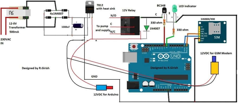
The circuit consists of power supply, which powers the whole setup.
The Arduino is the brain of the project which take decisions and GSM modem which sends and receives text SMS and communicate with the user and relay which controls the motor.
How it Works
Note: Please use at least 10K resistor at the base of the BC548 transistor, 330 Ohms is too low.
The transformer step down the 230VAC to 12VAC and bridge rectifier convert AC onto DC current and the current passes through an electrolytic capacitor to smooth the power supply.
A fixed 12V voltage regulator gives power to arduino, GSM modem and relay. The GSM modem is connected to arduino at pin #0 and pin #1, which are RX and TX respectively.
The RX of GSM is connected to TX of arduino and TX of GSM is connected to RX of arduino. If you are confused, just look at the below diagram, misconnection will not send or receive SMS.
ARDUINO TX----------------------RX GSM modem
RX----------------------TX
Ground to ground connection is also established between arduino and GSM modem.
Try to get a male jack power connector for the GSM and arduino, if not just solder the wires directly from power supply to arduino and GSM, which might increase the mess in the project.
The transistor drives the relay and the diode protects the circuit from high voltage spikes while switching the relay ON/OFF.
The LED indicator shows the status of the relay. If the LED glows the relay activated and if the LED is off, the relay is deactivated.
Insert a valid SIM on the GSM modem and try to take advantage of the offers availed by the network provider for SMS such as rate cutters, which will reduce the expenses for SMS.
Program Code:
//---------------- Program developed by R.Girish ----------------//

int LED   = 8;    // Status LED pin
int motor = 9;    // Motor relay control pin

int temp = 0;     // Flag to indicate end of command reception
int i    = 0;     // Index for command buffer

char str[15];     // Buffer to store received SMS command

//----------------------------------------------------------------
void setup()
{
  Serial.begin(9600);          // GSM module baud rate

  pinMode(motor, OUTPUT);     // Motor relay output
  pinMode(LED, OUTPUT);       // LED output

  digitalWrite(motor, LOW);   // Motor OFF initially
  digitalWrite(LED, LOW);     // LED OFF initially

  // Give GSM module enough time to register to network
  delay(20000);
  delay(20000);
  delay(20000);

  // Enable new SMS indication directly on serial
  Serial.println("AT+CNMI=2,2,0,0,0");
  delay(1000);

  // Set SMS text mode
  Serial.println("AT+CMGF=1");
  delay(500);

  // Send startup confirmation SMS
  Serial.println("AT+CMGS="+91xxxxxxxxxx"r"); // Replace x with your mobile number
  delay(1000);
  Serial.println("System is ready to receive commands.");
  delay(100);
  Serial.println((char)26);   // CTRL+Z to send SMS
  delay(1000);
}

//----------------------------------------------------------------
void loop()
{
  // If a full command is received
  if (temp == 1)
  {
    check();        // Process the received command
    temp = 0;       // Reset flag
    i = 0;          // Reset buffer index
    delay(1000);    // Small delay for stability
  }
}

//----------------------------------------------------------------
// Automatically called when serial data is received
void serialEvent()
{
  while (Serial.available())
  {
    // Look for starting delimiter '/'
    if (Serial.find("/"))
    {
      delay(1000);  // Wait for complete message

      while (Serial.available())
      {
        char inChar = Serial.read();
        str[i++] = inChar;   // Store character

        // Look for ending delimiter '/'
        if (inChar == '/')
        {
          temp = 1;          // Command received completely
          return;
        }
      }
    }
  }
}

//----------------------------------------------------------------
// Function to compare received command and take action
void check()
{
  // Command: motor on
  if (!(strncmp(str, "motor on", 8)))
  {
    digitalWrite(motor, HIGH);   // Turn motor ON
    digitalWrite(LED, HIGH);     // LED ON

    delay(1000);
    Serial.println("AT+CMGS="+91xxxxxxxxxx"r");
    delay(1000);
    Serial.println("Motor Activated");
    delay(100);
    Serial.println((char)26);
    delay(1000);
  }

  // Command: motor off
  else if (!(strncmp(str, "motor off", 9)))
  {
    digitalWrite(motor, LOW);    // Turn motor OFF
    digitalWrite(LED, LOW);      // LED OFF

    delay(1000);
    Serial.println("AT+CMGS="+91xxxxxxxxxx"r");
    delay(1000);
    Serial.println("Motor deactivated");
    delay(100);
    Serial.println((char)26);
    delay(1000);
  }

  // Command: test
  else if (!(strncmp(str, "test", 4)))
  {
    Serial.println("AT+CMGS="+91xxxxxxxxxx"r");
    delay(1000);
    Serial.println("The System is Working Fine.");
    delay(100);
    Serial.println((char)26);
    delay(1000);
  }
}

//---------------- Program developed by R.Girish ----------------//
NOTE 1: While compiling the program it shows a warning, which you can ignore it. The program is verified and tested.
NOTE 2: Please remove TX and RX connection from arduino while uploading the code.
NOTE 3: Replace “xxxxxxxxxxxxx” with recipient’s phone number in 4 places in the program.
NOTE 4: Please purchase a GSM modem without power button in the module; in case of power failure it won’t latch in into mobile network unless you manually press the button, so avoid such type of GSM modems. The GSM modem one without power button will latch into mobile network directly after power retains.
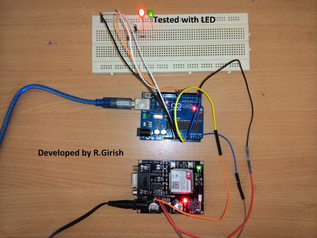
Author’s Prototype of GSM Pump Motor Controller Circuit:
How to use the above setup:
• Send /motor on/ SMS from your cellphone to activate the relay.
• Send /motor off/ SMS to deactivate the relay.
• Send /test/ SMS for testing the response from the circuit.
Make sure you start the command with”/” and end with “/” otherwise it won’t accept as valid request.
• /motor on/ will turn ON the relay and return with an acknowledgement SMS “Motor Activated.”
• /motor off/ will turn off the relay and return with an acknowledgement SMS “Motor Deactivated.”
• If you send /test/ it will return with an acknowledgement SMS “The System is Working Fine.”
• The above message signifies that your setup is working fine.
• If no acknowledgement is returned to you can assume that no action is preceded on the motor and you may troubleshoot the problems.
• After powering the setup ON wait for 1 minute the system will send an acknowledgement SMS “System is ready to accept commands.” once you receive this SMS your project is ready to serve.
The above commands are fool proof and never trigger the motor falsely, the setup will not respond any SMS other than the above specified commends.
Improving the above Concept
This above GSM pump application circuit attracted lots of readers and we have received tons of queries and suggestions. One of the avid readers of this website Mr.Gandhi suggested a good improvement to the prior design.
SMS Acknowledgement When Motor is Actually ON
The improvement is all about the revert acknowledgement, where the user will receive a SMS response in his cellphone from the GSM pump controller system when a user sends a valid SMS comment.
The existing design sends an acknowledgement SMS to the user independent of the actual state of the relay i.e. ON/OFF.
The new design change suggested by Mr.Gandhi checks the state of the relay whether the relay is physically switched its state or not.
The change as per this new GSM water pump controller design can be implemented to the previous design without much hassle by adding a feedback system as shown in the schematic and uploading the new code.
Circuit Diagram:
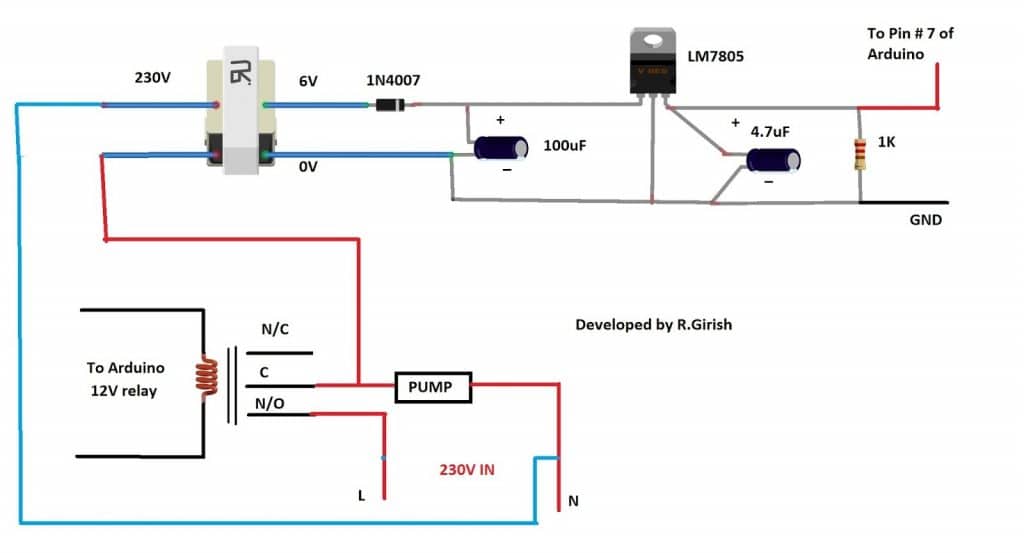
When we send SMS command “/MOTOR ON/” the pin # 9 goes high and trigger the relay ON. If the relay connects the common and N/O pins the pump starts and also turns ON the transformer which will give +5 at the output.
The +5V signal is fed to pin # 7 which will confirm and return with an acknowledgement “Motor activated”.
When we send “/MOTOR OFF/” the pin # 9 turns LOW and relay disconnects the common and N/O pins, this will turn off the pump as well as the connected transformer. The output at pin # 7 goes LOW and returns with an acknowledgement “Motor deactivated”.
If no acknowledgement SMS is received in your cellphone, we can confirm that no action was taken and the pump is at the last requested state, you may go to the site and troubleshoot or no acknowledgement is received due power cut.
Program Code:
//---------------- Program developed by R.Girish ----------------//

// Pin definitions (do NOT change to keep circuit intact)
int motor = 8;      // Relay / Motor control pin
int LED   = 9;      // Status LED
int ack   = 7;      // Acknowledgement feedback pin

// Variables for SMS parsing
int temp = 0;       // Flag to indicate full command received
int i = 0;          // Index for character buffer

char str[15];       // Buffer to store incoming SMS command

void setup()
{
  // Initialize serial communication with GSM module
  Serial.begin(9600);

  // Pin configuration
  pinMode(ack, INPUT);
  pinMode(motor, OUTPUT);
  pinMode(LED, OUTPUT);

  // Ensure outputs start in OFF state
  digitalWrite(motor, LOW);
  digitalWrite(LED, LOW);

  // GSM module startup delay (network registration time)
  delay(20000);
  delay(20000);
  delay(20000);

  // Configure GSM module for direct SMS display
  Serial.println("AT+CNMI=2,2,0,0,0");
  delay(1000);

  // Set SMS text mode
  Serial.println("AT+CMGF=1");
  delay(500);

  // Send startup confirmation SMS
  Serial.println("AT+CMGS="+91xxxxxxxxxx"r"); // Replace with your number
  delay(1000);
  Serial.println("System is ready to receive commands.");
  delay(100);
  Serial.println((char)26);   // CTRL+Z to send SMS
  delay(1000);
}

void loop()
{
  // If a complete command is received
  if (temp == 1)
  {
    check();        // Process the command
    temp = 0;       // Reset flag
    i = 0;          // Reset buffer index
    memset(str, 0, sizeof(str)); // Clear buffer
    delay(1000);
  }
}

// This function automatically runs when serial data arrives
void serialEvent()
{
  while (Serial.available())
  {
    // Look for starting delimiter '/'
    if (Serial.find("/"))
    {
      delay(1000);

      while (Serial.available())
      {
        char inChar = Serial.read();

        // Store character safely in buffer
        if (i < sizeof(str) - 1)
        {
          str[i++] = inChar;
          str[i] = ' ';   // Always keep string terminated
        }

        // End delimiter '/' detected
        if (inChar == '/')
        {
          temp = 1;        // Signal full command received
          return;
        }
      }
    }
  }
}

// Command processing function
void check()
{
  // Turn motor ON command
  if (!(strncmp(str, "motor on", 8)))
  {
    digitalWrite(motor, HIGH);
    delay(100);

    // Check acknowledgement feedback
    if (digitalRead(ack) == 1)
    {
      digitalWrite(LED, HIGH);
      delay(1000);

      Serial.println("AT+CMGS="+91xxxxxxxxxx"r");
      delay(1000);
      Serial.println("Motor Activated");
      delay(100);
      Serial.println((char)26);
      delay(1000);
    }
  }

  // Turn motor OFF command
  else if (!(strncmp(str, "motor off", 9)))
  {
    digitalWrite(motor, LOW);
    delay(5000);

    if (digitalRead(ack) == 0)
    {
      digitalWrite(LED, LOW);
      delay(1000);

      Serial.println("AT+CMGS="+91xxxxxxxxxx"r");
      delay(1000);
      Serial.println("Motor deactivated");
      delay(100);
      Serial.println((char)26);
      delay(1000);
    }
  }

  // System test command
  else if (!(strncmp(str, "test", 4)))
  {
    Serial.println("AT+CMGS="+91xxxxxxxxxx"r");
    delay(1000);
    Serial.println("The System is Working Fine.");
    delay(100);
    Serial.println((char)26);
    delay(1000);
  }
}

//---------------- Program developed by R.Girish ----------------//
The above implementation is not practically tested, but the author is cent percent sure that above idea will work. If readers found any issues with the above improvement can express through the comment section.
Part List
1) Transformer step down 12-0V
2) Diodes IN4007 x5
3) LM7812 x1
4) Relay 12V x1
5) BC548 Transistor x1
6) Electrolytic Capacitor 1000uF x1
7) GSM module: SIM 800 or SIM 900 model
8) 330 Ohm Resistor x2
9) LED RED/GREEN x1
10) Arduino Uno or Arduino nano or Arduino Mega
11) DC male jack x2
Video Clip:
Integrating with 3 Phase Motors
I have been receiving many requests to upgrade the relay stage for the above design so that it becomes compatible for operating 3 phase motors using GSM cell phone commands.
Therefore I decided to design the required circuit which will hopefully be able to switch ON and switch OFF a given 3 phase motors having the typical start and stop contactor mechanism.
The following figure shows how to configure the design using an IC 4017 circuit.
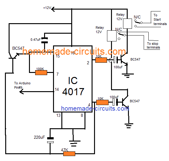
NOTE: The 100uF /10K and 220uF and 47K values may need some adjustments in order ensure the correct amount of delay for the respective transistors and relay stages.


Comments
Swagatam ! You’re the one of the greatest blessings of God to this earth. My all prayers for you..!
Have a wonderful day.!
Thank you very much Eman. The pleasure is all mine!!
The usb frm laptop to arduino provides 12v ?
And again a nice and useful project .
So if I have to connect this to start and stop configuration then I just need to connect the relay contacts to the button with appropriate contact rating right????
Thanks very much, yes that’s correct, but the relay action will need to be momentary, the “start” will need to be momentary ON (relay#1), and stop will need to be momentary OFF (relay#2)
Hello sir can you please share the circuit diagram for the same project,but connecting 3 phase motor at the end in place of single phase of motor or 230v motor..
Thank you
Hello Madhu shankar, are you using a contactor for the 3 phase motor, having start stop buttons??
Thanks sir…
Can you suggest any specific Arduino IDE sotware version.
I compiled the code using ARDUINO IDE 1.0.3 and 1.8.0
And i am not receiving any acknowledgement message in any of it. However, i didnt have the relay connected yet.
sir, while compiling and uploading, the arduino software is showing following errors:
software: Arduino: 1.8.5 (Windows Store 1.8.10.0) (Windows 10), Board: “Arduino/Genuino Uno”
errors:
C:\Users\Hi\Downloads\WOCS\WOCS\WOCS.ino: In function ‘void serialEvent()’:
C:\Users\Hi\Downloads\WOCS\WOCS\WOCS.ino:41:19: warning: deprecated conversion from string constant to ‘char*’ [-Wwrite-strings]
if(Serial.find(“/”))
^
Sketch uses 2902 bytes (8%) of program storage space. Maximum is 32256 bytes.
Global variables use 383 bytes (18%) of dynamic memory, leaving 1665 bytes for local variables. Maximum is 2048 bytes.
avrdude: verification error, first mismatch at byte 0x0000
0x62 != 0x0c
avrdude: verification error; content mismatch
avrdude: verification error; content mismatch
This report would have more information with
“Show verbose output during compilation”
option enabled in File -> Preferences.
Hi Suman,
These are warnings, noting to worry about it:
———————————————
C:\Users\Hi\Downloads\WOCS\WOCS\WOCS.ino: In function ‘void serialEvent()’:
C:\Users\Hi\Downloads\WOCS\WOCS\WOCS.ino:41:19: warning: deprecated conversion from string constant to ‘char*’ [-Wwrite-strings]
if(Serial.find(“/”))
——————————————–
But you should have compiled the code successfully, there are no errors in the code.
If your issue is while uploading the code to Arduino, then check that you have proper drivers is installed to your PC or any hardware issue with your Arduino (Try uploading a blink sketch).
Regards
hello sir,
i am having problem with the output..i am using gsm 900A gsm module and arduino UNO for the project..after completion of programming and when i turn on the circuit i am getting the message “SYSTEM IS READY TO RECEIVE THE COMMANDS” ,but when i send /motor on/ or /motor off/ the i am not getting output..it mean motor not getting turn on,as well as replay message is not getting..but when i calling to number which one is in gsm module its gets ringing..can you help me to complete my project..
Thank you
Hi madhu shankar,
Try these two codes:
https://www.homemade-circuits.com/how-to-receive-sms-using-gsm-modem-and/
https://www.homemade-circuits.com/how-to-send-sms-using-gsm-modem-and/
Check these two functionality with your GSM module it should work fine, if any issues any replace it.
Regards
Hi girish sir,
I m new in the learning stage about hobby of microcontroller programing. I want any program code that my microcontroller work / read the instructions from a specific mobile number and the mobile number can be changed by re-programming or via sms what ever your convinces. plz send me that code on my reply or my email – rkrun1987@gmail.com
Thanks in advance.
Sir I want the code for wireless closed loop speed control of DC motor . Here I am using GSM, Arduino and h bridge module. Also I want to implement the pid controller in the above program. Can you help me?
Jyoti,
creating customized code will need a fee to be paid for the service, presently the price is 10/- INR per line of code
hello sir,
thanxx for tutorial … sir I want to on and off motor using missed call based please tell me how can I do thiss??can u send me code for thiss??
Ravindra,
you can try eh following circuit
blog/gsm-based-irrigation-circuit-using-cellphone-missed-calls-and-arduino/
This following AT command AT+CLIP=1 in this pic has caller IDENTIFICATION i.e., getting the number of caller to module…so if we try to match this number to our if else code and we can write if else condition… like if matched with that number as receiving number LED=HIGH, we can control led on n off with missed call
IAM facing a problem with my GSM Sim 900A when I give it /Motor ON/ message it’s taking and giving output, but when I give off message it’s not responding…i.e.,it’s only taking the 1st command and not responding to the second….when I use the same code for other gsm module it’s working fine for 1st and second messages of motor on and off…when I ask shopkeeper to replace he is saying it will not behave like that and blaming me that my code is wrong and he is covering himself when it is responding to 1st command it will respond to 2nd also it won’t do half work…but code 100% correct..as it worked for u all and worked for me in other gsm mod.. please say what to do.is there any minor error on my side?.
Hi Rahul,
I am sure that it is a hardware issue with GSM module. Try getting replaced especially if you are going to represent the project for your final year.
If it responded to your first comment, it would not be your mistake most probably.
Regards
I will forward this message to Mr. GR, he will reply you soon.
Can we write a program to start a Motor by first ring and stop it with second ring…and we must get acknowledgement message after each ring whether motor Is on or off like ur previous program
Help me write this code
Hi rahul,
I will try to design as per your requirements soon.
Regards
Ok,sir…and this will help farmers a lot because some farmers are not literate enough to send message and turn on motor,if it’s a missed call it will be easy and simple for them…
I will forward this to Mr. GR, if it is possible he will revert with a reply.
Can i get the required material list and if there is any link where i can get the same at the best price?
Mainly i want link to the gsm module.
Have you used gsm module or gsm modem?
Please reply asap as i need help with my College irrigation project
The parts list has been updated at the end of the post
As mentioned in the article, it is a GSM modem that is used in the project.
The GSM modem can be easily purchased from any online store.
If you wish you can purchase the entire project for Rs.5000/- from us (all inclusive)
I’ll try to get the entire parts list from the author of the article Mr. GR, and update it soon…
Hi, Swagatam
To switch on/off a single phase submersible pump set, I made a little change in the code and it is working fine. The changes I made are :
int motor = 8; // main power suppy to pump unit via relay
int LED = 9;
int start = 10;//for momentary shorting of start button
int temp=0;
int i=0;
int ack=7; //will act as dry run detector
char str[15];
void setup()
{
Serial.begin(9600);
pinMode(ack,INPUT);
pinMode(motor,OUTPUT);
pinMode(LED,OUTPUT);
pinMode(start,OUTPUT);
digitalWrite(motor,LOW);
digitalWrite(LED,LOW);
digitalWrite(start,LOW);
delay(20000);
delay(20000);
delay(20000);
Serial.println(“AT+CNMI=2,2,0,0,0”);
delay(1000);
Serial.println(“AT+CMGF=1”);
delay(500);
Serial.println(“AT+CMGS=\”+91xxxxxxxxxx\”\r”); // Replace x with mobile number
delay(1000);
Serial.println(“System is ready to receive commands.”);// The SMS text you want to send
delay(100);
Serial.println((char)26); // ASCII code of CTRL+Z
delay(1000);
}
void loop()
{
if(temp==1)
{
check();
temp=0;
i=0;
delay(1000);
}
}
void serialEvent()
{
while(Serial.available())
{
if(Serial.find(“/”))
{
delay(1000);
while (Serial.available())
{
char inChar=Serial.read();
str[i++]=inChar;
if(inChar==’/’)
{
temp=1;
return;
}
}
}
}
}
void check()
{
if(!(strncmp(str,”motor on”,8)))
{
digitalWrite(motor,HIGH);
delay(100);
digitalWrite(start,HIGH);
delay(5000);
digitalWrite(start,LOW);
if(digitalRead(ack)==1)
{
digitalWrite(LED,HIGH);
delay(1000);
Serial.println(“AT+CMGS=\”+91xxxxxxxxxx\”\r”); // Replace x with mobile number
delay(1000);
Serial.println(“Motor Activated”);// The SMS text you want to send
delay(100);
Serial.println((char)26); // ASCII code of CTRL+Z
delay(1000);
}
if(digitalRead(ack)==0)
{
digitalWrite(motor,LOW);
delay(1000);
Serial.println(“AT+CMGS=\”+91xxxxxxxxxx\”\r”); // Replace x with mobile number
delay(1000);
Serial.println(“Motor Dryrun”);// The SMS text you want to send
delay(100);
Serial.println((char)26); // ASCII code of CTRL+Z
delay(1000);
}
rest of the code is same.
with regards
That’s wonderful Anupam, I am glad you could modify it and make it work you you…keep up the good work!
Hi Swagatam,
Thanks for your appreciation. By the way, I am also very much interested in Arduino Uno based LED moving message display. In fact I have built one with the help of projects available in net. But I do not find any way how to increase the number of rows. All such projects I came across are of 8 rows. As a result the characters are too small. There is scope in the sketch to increase the number of columns but not rows. Would you please help me in this regard.
With regards
Hi Anupam, I wish I could help you, but since I am not good with Arduino so I won’t be able to suggest you much in this regard. You can contact and request Mr. GR on his Facebook account and see if he can help.
Hi Swagatam,
I am very much glad to let you know when I changed the GSM module, the circuit is working fine as described. Many many thanks to you and Mr. Ragavan for extending your help. I would like to request you kindly give me suggestion how to modify the circuit as well as code/sketch to switch on and off a single phase Pump motor and three phase motor.
With regards
You are welcome Anupam, we are glad you could succeed, according to me you can use the same circuit and code for switching ON/OFF a single phase pump and also for a 3 phase, but for 3 phase replace the BC548 with a 2n2222, and the relay with a triple pole triple throw or TPTT relay, and wire the 3 contacts with the 3 phase supply connections accordingly.
By the way the author name is “Mr. Radhakrishnan” and not Mr. Ragavan 🙂
Hi Swagatam,
First of all I am extremely sorry for wrongly quoting the name of Mr. Radhakrishnan as Mr. Ragavan. Please convey my thanks to Mr. Radhakrishnan. By the way, I was supposed to let from you know how to switch on/off a single phase submersible pump motor and not a simple single phase pump motor. Please help me in this regard. Also please let me know how can the code be modified to accept messages from more than one mobile.
With regards
Hi Anupam,
You can send SMS commands to GSM module from any mobile phone, but you will receive the acknowledgements to number than you entered in the code.
Regards
*that not “than”
Hi Anupam, do you mean to say you want to know how to operate the submersible contactor “start”, “stop” buttons? I’ll try to figure it out if possible.
For the codes I will inquire with Mr. GR.
Hi Swagatam,
Thank you for your prompt reply. Yes, I want to operate the Start, Stop buttons of submersible pump starter. Also please let me know if the circuit and code can be modified to respond sms from multiple numbers.
With regards
OK,Mr. GR will reply you soon…
Hi, GR
I think the problem is with the GSM Modem. I bought SIM900A Dualband GSM/GPRS TTL MODULE for Arduino Raspberry Pi and other MCU from eBay. Is this type of module is alright ? If not, then please suggest what type of GSM module is needed . There was no message “System is ready to receive commands”. Moreover, When I tried to make call, the reply was subscriber is not reachable. Please tell me one thing, after inserting the SIM if 5 volt supply is applied to the module without connecting Tx and Rx to Arduino Rx and Tx respectively , should I not hear ring tone ? If I do not get ring tone on calling, is it due to the fault of GSM module?
With regards
Hi Swagatam,
I made the circuit and uploaded the sketch as described above but there is no response even if /test/ or /motor on/ SMS is send. Moreover, when I tried make call the response was “subscribe is not reachable” What could be the problem? Or where could be the possible error I made ? Please help.
With regards
Anupam Dasgupta
Hi Anupam,
The problem is probably with mobile network.
You must receive “System is ready to receive commands” from the GSM module after powering 1 to 2 minutes, only after then you able to control the motor/relay. If you did’t receive the mentioned acknowledgement SMS, your SMS commands won’t be accepted.
When you call to GSM modem, we must hear ring sound.
Also check the TX and RX pins once again.
Regards
Hi Anupam, I’ll forward this issue to Mr. GR, he’ll reply you soon….
Dear GR sir
I like your gsm based irrigation system and,your profile also
But I need to add more things in that irrigation projects,which is helpful for me, I need to implement some motorized valve to irrigate our farm land randomly when given commond by me,and also I need to check 3phase detection when power comes give 1 msg to me AC power on and when power failure give another msg to me No AC supply ,we using phase supervision relay and use NO NC contact of this relay for feedback also check status of flow water using flow switch
Hi Subhash,
Let me do some research, if all your mentioned points are feasible, I will make this project.
Regards
while compiling the code an error message – expected ‘)’ in string command. I could not go further. Please help me.
Hi, please check it now, and let me know if the problem is still there….
with the new code, there was no problem in compiling as well as uploading sketch. Rest will be informed as soon as I complete the project. One more thing I want to know from you that whether the project will work on 4G SIM or not ? If not, what are the modifications needed ? As 2G SIM is almost becoming obsolete. Please help your followers.
Hi, Anupam
The 4G sim will work if it is backward compatible with 2G network.
Most of 4G Sim should work well, except “Jio” because their network is “4G only” but you can try with Jio and mention your result in comment.
I used with BSNL 3G sim which is backward compatible with 2G and worked flawlessly.
Regards
Hi Anupam,
Can you please elaborate you request a bit more.
Regards
Hi, GR
Thank you for your reply. For want of GSM Modem (which I ordered online) I could not complete the project. On completion, I will experiment with JIO SIM and let you know the result. I would like to take this opportunity to request you to publish moving message led display circuit with arduino uno with code having scope for increasing both number of rows and column.
With regards.
I’ll forward this question to Mr.GR, he’ll reply soon.
dear sir . only this module it works is 10 km,so 20km how to works it with gsm module with motor pump
chintamani, in the request the distance of the pump is specified being at 10km distance, that does not mean the above circuit is restricted to 10km…since it is a GSM based the range can be infinite.
Friend i need dry run protection for this please provide the code ware i have to change
Hi, dry run protection will need to be a sensor based circuit, either a water sensor or heat sensor which can be attached with the motor along with a cut off circuit.
friend but i need message alert also so please provide the program
like one digital in put but that one reading after after 10 min’s from motor ON condition digital in put LOW that time motor and led OFF and send the message motor off due to dry run so please provide the that condition
OK friend, I’ll request Mr. GR to update the feature in the article.
Hi…
I am farmer and i want my farm pump set automatic start using GSM Mobile no android.
how many cost for this work.
If you interested so please help me or advise me.
please email me for cost and process.
Thanks .
Hi,
I have forwarded your email ID to Mr. GR, he will contact you soon with the reply.
friend i need three phase updating also include this project please do the help
replace the relay with a 3 contact relay..that’s all
hi sir
plz can you tell me the 12v relay can start 3 phase motor pump
use 3 relays in parallel, one relay for each phase, each relay contact must be rated at 30 amp…use TIP122 for the driver transistor, with 10K as the base resistor
deaer swagatam da i need to controll the speed of a 12volt dc car wiper motor.please describe any circuit for it which able to varies the speed but no effect on torque.
hope you understand my requirment……
thanks
Dear Kaushik, you can use the following concept for your requirement
https://www.homemade-circuits.com/2012/05/make-this-pwm-based-dc-motor-speed.html
HELLO GIRISH SIR
CAN U SEND THE CIRCUIT DIAGRAM OF THE PROJECT WITH NEAT EXPLANATION
Hello Bala, the circuit and the explanation are adequately presented in the part1/part2 versions of the article, you can refer to them to get an in-depth view of the idea.
part1 explains a controller that reverts an acknowledgement message when the remote unit is activated, whereas in part2 the same idea is further upgraded and allows the remote end to send a message to the user when the motor is actually activated making the process entirely foolproof.
Can it works on A6 module?
Can this program works on A6 module? Or sim 900?
I would recommend sim 900 or sim 800 module, because this project has been test with these modules.
I am assuming it must work on A6 module equally as it works on AT comments.
Regards
Hi Sir,
Same question as above that if we plan to use 4 relays,what shuold we change or add in the code?
Thanks a lot.
Hi, you can connect all the 4 relays in parallel, just make sure the driver transistor is replaced with an appropriately rated one.
MR GIRISH I AM WAITING FOR YOUR ADVICE …..PLEASE LET ME KNOW THE SOLUTION ASPS
DEAR SWAGATAM I NEED TO USE MY SPAIRE LAND FONE AS A GSM FONE …SO GET ME THE IDEA HOW TO DO ….I HAVE A SIM 800 GSM MNODULE …SHALL I USE IT FOR THAT?
Hi kaushik,
You can't use your landline phone as GSM phone. Landline phones aren't designed or can't be modified. However you can use your GSM module to function as a basic cell phone (GSM phone), which I will try to make a different article.
Regards
Mr.GR, will try to solve it for you
Hi kaushik,
I think 4G SIM don't work with SIM800/900 module, try to use only 2G SIM. In my prototype I've used BSNL 3G SIM (also 2G compatible) and it worked great. Make sure you 4G SIM is backward compatible with 2G network.
Regards
GIRISH SIR,
I HAVE NOTICE A PROBLEM…MY PROJECT IS WORKING FINE .BUT NOW I NOTICE WHEN I PUT THE 4G SIM (AIRTEL) INSTEAD OFF 2G SIM IT DON'T REVERT WITH THE SPECIFIED COMMEND LIKE"SYSTEM IS REDY TO RECCIVE THE COMMEND",MOTOR IS ACTIVATED OR DEACTIVATED" …..IN-SPITE OF IT SMS COMES "NULL" …..BUT IN 2G SIM IT WORKS AS YOU DESCRIBE …ALSO IT RESPOND ON 4G SIM…..WHY IT HAPPENS ? HOW TO RECOVER ?
HOPE YOU UNDERSTOOD MY ISSUE?????
SIR…THANKS FOR YOUR UPDATES…I UNDERSTAND WHAT YOU ASKED…..IT MEAN AFTER ADDING THE NEW NUMBER AT PROGRAM SKETCH NEED TO BE RE-UPLOAD TO THE ARDUINO. AT SAME TIME IT ERASE THE OLD & REPLACE WITH THE NEW POGRAM?…SHALL I CORRECT ?
My next project fire alart system which also described by mr girish…….for that i want to remove the old pogram and reload the new pogram…..how its possible please describe ???next another question is how to change the phone no for the exsisting project….please help
MR.SWAGATAM…..SHALL I BE USE THIS arduino TO MAKE A NEXT ANOTHER PROJECT WHICH I USED IN MY LAST PROJECT ? PLEASE BRIEF ME HOW TO REPLACE THE OLD PROGRAM TO NEW ….PLEASE PLEASE
Hi,
Just upload your new code, the old code will get erased.
Regards
please specify the details of your next project…
GIRISH SIR ,
MY PROJECT IS WORKING FINE …..NOW I WANT TO CHANGE THE PHONE NO & WANT TO PUT "MAINS " INSTEAD OF "MOTOR"……HOW TO IMPLIMENT PLEASE GUIDE ME …..
Hi kaushik,
Replace the phone number which you have entered in code with new one.
Replace the word MOTOR with MAINS in the code, don't change any thing else.
Regards
MR .GIRISH
MY CIRCUIT IS WORKING FINE ….AGAIN THANKS FOR YOUR CO-ORDINATION ..SIR.I HAVE AN IDEA TO MODIFIED WITH THIS CIRCUIT ….I WANT TO ADD TWO SENSOR WHICH INTERLOCK WITH THIS CIRCUIT….MOTOR CAN BE AUTOMATICALLY STOP INCASE THE WATER LAVEL IS MINIMISED THEN THE SPECIFIED LAVAL AT RESERVER OR IF MAXIMISED AT THE STORAGE TANK.AND IN BOTH CASE MASSAGE CAN BE SENT….PLEASE GET ME THE SOLUTION
Glad to know it's working Kaushik.
If Mr.GR finds it comfortable and if he is not busy, he will surely look into it
DEAR MR. GIRISH ….I HAVE BOUGHT THE ARDUINO UNO 3 WITH ATMEGA 328 BOARD ….AFTER COPY THE PROGRAM ..SAVE AND COMPILE THE PROGRAM TO ARDUINO ….I HAVE DONE AS FOLLOWS——
1.USING IDE 1.0.3 VERSION AT WINDOWS 7 LAPTOP.
2.COPY THE PROGRAM FROM YOUR DESCRIBED BLOG.
3.REPLACE THE PHONE NO AS YOU HAD TOLD .
Serial.println("AT+CMGS="+91xxxxxxxxxx"r"); // Replace x with mobile number
IN ABOVE LINE PUT MY PHONE NO AND DELETE THE LAST TEXT COMMENT FOR ALL
4.BEFORE COMPILING THE LED NEAR USB CONNECTOR HAS GOT FLASHING BUT AFTER COMPILING I NOTICE IT STOPE TO FLASH …..
SIR ….IS ABOVE STEPS ARE ATTEMPTING CORRECT ?IF ANT MISTAKE PLEASE ASK THE RECTIFICATION PROCESS….
SHALL I GOT YOUR MOBILE NO ?IT WILL HELP ME MORE OF COURSE IF YOU DON'T MIND?
Hi kaushik,
You have done everything right. The two LEDs are Tx and Rx, which will glow while your code is being uploaded to arduino and stop glowing after the code is uploaded.
Regards
GR sir
i am gandhi,my hobby to do the electronics projects,its really very useful to agri pump on and off.i use your code with gsm perfectly 9th digital pin led working based on the sms command and serial monitor i got the acknlowdgement while i send "/test/".i need the technical help 4m your side.weather the relay which is connected to the motor is on or not.just we want to know the status through gsm to our mobile sim number via sms not in serial monitor means how i wants to modify the program.guide me when ever u found free time.
thanks
Hi Gandhi,
I understood your request, I will try to update the code with schematic soon.
You want to receive the acknowledgment only after the motor is turned on physically and not just after Sending SMS commands.
Regards
BRO…..THANKX FOR YOUR COORDINATION ,ONE MORE DOUBT IS WHICH NUMBER HAS TO BE PUT TO THE PROGRAM IN THE PLACE OF "XXXXXX"…….THE NUMBER FROM WICH I SENT SMS OR WHICH THE SIM TO BE INSERT TO THE MODULE?
Hi kaushik,
You have to place your phone number from where you send SMS to GSM modem.
Regards
thank you to both of you ;i will try this ,if faced any trouble then please have to be help me to fulfill this project.
Hi kaushik, we will help you to accomplishing the project, you may ask any number of queries.
Regards
MR.GIRISH I AM WAITING FOR YOUR REPLY….I BOUGHT ALL THE COMPONENT BUT DUE TO THIS DOUBT I CANNOT CONSTRUCTE MY PROJECT……PLEASE REPLY AT MOST EARLIEST……….
Kaushik, Please refer to the above comment for the reply.
swagatam,
i have a doubt,can you guide me sir,in program front what will be the 1st line of program & what will be the last line of program to be copy for uploaded?
Hi kaushik,
The program starts with
//—————-Program developed by R.GR————//
and end with the same. The mentioned line is not necessary to operate the project.
You can copy the codes between the above mentioned line.
Regards
kaushik, this article was submitted by Mr. girish who is one of the authors of this blog, I hope he will find your comment and respond soon.
Dear swagatam ,
Can you ask me ,how many times can i pogeram a aurdino ,or is there any chance to rectify the pogram after uploded
Dear Kaushik,
there are no such restrictions, you can program as many times as you want and rectify the codes anytime after the upload
Good morning,
Very good work. I want to ask if I want to put four relay;
What change in the code;
And command if(!(strncmp(str,"motor on",8))). The number 8 it says;
I tried the code on A6 GSM and it works fine
Thank you very much.
Thank you Konstantinos, I hope Mr. GR will see this comment and revert soon.
Good morning,
Very good work. I want to ask if I want to put four relay;
What change in the code;
And command if(!(strncmp(str,"motor on",8))). The number 8 it says;
I tried the code on A6 GSM and it works fine.
Thank you very much.
But sir I shouldn't get any ring back sir.
I think I purchage your module.
Please sir send me your link from which you buy your module.
Hi ranjan,
I don't remember URL, but I purchased from amazon. Try searching SIM 800 and you may see a module similar to mine which is shown the link:
https://www.homemade-circuits.com/2016/09/how-to-send-sms-using-gsm-modem-and.html
Regards
My link from which I purchase gsm module.
http://www.amazon.in/gp/aw/d/B01MSVR7NJ/ref=mp_s_a_1_17?ie=UTF8&qid=1487232078&sr=8-17&pi=AC_SX118_SY170_QL70&keywords=gsm+module#
Hi ranjan,
Looks good,
Insert the sim and call the number, you should get ring back. If this is done, try to send basic sms using your module from the link in previous comments.
Regards
In this gsm module there are 3 led red,green,yellow and a buzzer.When i give supply to the gsm module the buzer is beep and red and yellow led is blink fast 3-4 time then off up to 30sec and the green led is always on
It has not any power button
I also give phone number with our country code i.e.+91
Its network led doesn't blink in 3 second
Hi Ranjan,
You have a slightly different kind of GSM modem than what I imagined, no problem.
you can test the GSM modem by following the link in the previous comment and comment your issues, let's resolve it.
Regards.
How I share the picture
can you please share your GSM modem's picture top and bottom view and share the link. Let me take a look….
Hi ranjan,
if the network LED is not blinking for every 3 second, there may be chance that your GSM modem is defective or the SIM is defective. Please confirm this before proceeding further steps.
Your may check your GSM modem by sending basic SMS:
https://www.homemade-circuits.com/2016/09/how-to-send-sms-using-gsm-modem-and.html
If your GSM modem can send SMS then its error with your wire connection.
Regards
Dear GR sir,
I copy the program and replace "xxxxxxxx" by phone no. and compiled it,uploaded by aurdino software 1.0.3 version
Then I use gsm module sim800a
It has 4 no. of pin Tx,Rx,gnd,5v
I connect
Rx of aurdino——->Tx of gsm
Tx of aurdino——->Rx of gsm
gnd of aurdino——->gnd of gsm
5V of aurdino——->5V of gsm
Then give the supply to aurdino uno board
I use airtel 4g sim with 2g accessible
But it doesn't give any reply to the programmed phone number
Hi Ranjan,
Replace "XXXXX" with your phone number with +91 country code at beginning.
Do NOT use 5V arduino supply to GSM modem. You should power it separately from a wall adapter with 9V.
Let me know whether your GSM modem has power button, if so you should to press the power button for 3 seconds.
Make sure that your sim card is latched into mobile network. You can confirm this by looking at network LED blinking once every 3 seconds and not blinking at faster rate continuously.
Regards
please help me sir i want to give this project in my final year project
I study in diploma 3rd year in ELECTRICAL
Hi ranjan,
Please check your wire connections. We can't spot the reason why your circuit didn't work. Please elaborate your quires.
Regards
Why gsm module don't send any acknowledgement message
Dear Sir,
As you told Circuit is working sir, I got the commend(System is ready to accept commands)when we switch "ON" the circuit.
But after getting that how many calls I have to do? I tried calling that number (call is going) but Relay is not getting activated and LED is also not glowing. Please help me to solve this problem sir.
Best Regards
PG Ragavandir
Hi ragavan,
I am glad that it worked.
It can be controlled only by SMS
Regards.
Dear Sir,
Working sir, thanks a lot, "HATS OFF" for both,
but this is working through only sending SMS "motor ON" and "motor OFF"? or we can Call and control also?
Best Regards
PG Ragavandir
Hi ragavan,
Send sms /motor on/, /motor off/
Starting and ending with "/".
Regards
Dear Sir,
Thanks for your reply, sorry for my late reply.
I have to send SMS from my phone to the SIM in GSM number like "Motor ON & Motor OFF" right?
Your right as you told I have typed in serial monitor only sir, sorry.
Now will try and tell the result.
Best Regards
PG Ragavandir
Hi ragavan,
I think you are totally confused!!!
you must send SMS commands as mentioned earlier from your mobile (the number which you have entered in the code) to the number of sim card which you have inserted in GSM module. That's all, and you will receive an acknowledgement SMS from GSM module. Every time you power on you will get that test SMS.
Command prompt??? you mean serial monitor? No need to type any comment on that and no need to connect arduino to PC other than uploading the code.
Any problem we are here to help.
Best Regards
Dear Swagatam Sit & Radhakrishnan Sir,
Thanks for your immediate reply.
As you told I did sir but sorry for saying, same message is coming as ready,
Now I connected Arduino with PC to check comment prompt. In that I gave comment as your instruction but same happening sir. Relay is not switching "ON or OFF"
Sir if possible can you please share your phone number or Gmail ID so that call or chat. Please help
Best Regards
PG Ragavandir
Hi Ragavan,
Your system is working fine if you receive "System is ready to accept commands".
You must send text SMS to the number not calling.
Use /motor on/ to activate the relay.
Use /motor off/ to deactivate the relay.
Use /test/ for testing the response from the circuit.
Start the command with”/” and end with “/” otherwise it won’t accept as valid request.
Try to read the complete article as it is mentioned in the post 🙂
Regards
Dear Ragavan, Mr. GR will answer your question soon.
Dear Sir,
Thanks for your response for this circuit, and I thank Mr. Radhakrishnan too.
I will try to make this, If I achieved this for sure will tell your name & Mr. Radhakrishnan's name to whom all I try to help.
Great for you both, may GOD bless
Thanks & Best Regards
PG Ragavandir
You are welcome Ragavan! Wish you all the best…
Instead of using PIR .I have one idea by using IR ,PHOTO DIODE and CD4017…when we give one postive pulse to PIN 14 the CD 4017 One channel will active i seen this circuit in Infrared using on off for home appliance…
.I'm modifying the circuit..I'm using IR bulb it will continuously glow when we enter inside the ir will reflect the signal to photodiode . The photo diode will give signal to PNP transistor to activate the CD4017..now the o/p will be active…when we go outside of the room the reflection will happen again and the o/p will be off…
I didn't try this circuit….If it's correct means i will try sir….pls give me SUGGESTIONS sir….
yes you can alternatively try other types of sensors for sensing an intrusion.
you can try a proximity detector circuit for the same.
surely a 4017 flip flop circuit can be used for implementing the toggling action of a relay by integrating it with any form of intrusion detector sensor.
If u r using pir circuit pls give the link id sir
Already i connected sir…10uf 63v electrolyatic capacitor…same prblm coming sir…..when i enter inside it glowing well the flashing will be stop…and after 3 min it will be off …after 1 hour it will be flashing.
Sensor problem means it won't work when we enter…
Kesava, I am glad you could correct the fault, however flashing should not have happened, that's something you will have to identify yourself, or you can change the PIR and see if the fault persists.
increasing the capacitor effectively grounded the stray signals which was causing the fluctuations, and therefore the flashing stopped
In u r PIR post i see one..ckt
In the transistor emitter and base across one capacitor 25V 470uf…
I make in my circuit..Now its working fine sir…
I want to know the reason ..
1.Y its making flashing while I'm using 10uf capacitor…
2.when we increase capacitor value it not flashing and working good..
What is the function of capacitor in this PIR circuit…
Now its working well..
I'm so happy sir..
Thank u very much sir..
anode will connect with PIR o/p, and cathode towards the transistor base with the resistor in series…the resistor can come at the LeD anode or at the LeD cathode.
PIR——>|—-^^^^—–base
PIR——^^^^—–>|—–base
I'm using NPN transistor …
Transistor base want to connect ANODE of LED ?
and CATHODE of led to PIR o/p….
We want to use resistor & led in series or only led in series
try connecting a filter capacitor immediately across the supply pins of the PIR, and also connect an LED in series with the transistor base and PIR o/p pin…..just to monitor the PIR output response….
Sir I need automatic water tank overflow control circuit Using microcontroller with full detailed coding.
Naresh, if possible I'll try to include it soon.
Sir i have one doubt abt PIR SENSOR…
I bought from Amazon.Using rest room Pir sensor out..connected with transistor & relay its working well…but sometimes its flashing..
While flashing time i enter inside its working well…whats the reason for flashing..
It could be due to some stray signal pick up, try connecting a 10uF or any high value capacitor across base/emitter of the transistor and check the response
Is there any book available sir
you can find many good online tutorials with videos…
Hai sir…I'm new for Aurdino…
So pls tell the Model no of Aurdino…
And How to program the Aurdino sir…
Hi Kesava, you will have to go through an extensive course to learn Arduino, it cannot be taught here in comments or through a few articles.