In the following post I have explained a simple circuit idea which can be used for generating free electrical energy for illuminating a few safety flashing LEDs on a Bicycle.
The Circuit Concept
A bicycle like any other modern vehicle needs provision of lighting system for its use at night or cycling in lesser light. Usually a bicycle is designed with the front light and the back light, being red in colour. The front light is often fitted with a cycle using a dynamo system.
A dynamo generates alternating current by causing a friction in the tyre.
This actually slows down the speed and the cyclist has to paddle with more power to generate speed. Another kind of lighting can run through battery which is usually a detachable device.
But what if a situation when there is no need of dynamo, neither depending on battery for a bicycle light?
The introduction of an innovative system called ‘Safety Flashing Light’ has solved the purpose.
It not only helps to eradicate the concept of battery or dynamo system; it indeed offers more powerful light and longer standby compared to the other types.
This new electrical generating system has already created a sparkle in the bicycle market for its efficiency and ease-of-use.
How the Free Energy Bicycle Generator with Safety Flashing Light Works?
The Safety Flashing Light is designed in a way to handle all possible situations when driving a bicycle. For instance, a cycle when running in slower speed; two white-front LEDs and three red-rear LEDs flashes to make others notice on its presence.
In the case of standby mode, when the rear-wheel break is applied, the front and back LEDs gets activated. The lights are very bright and it can be noticed even in daylight.
Even no maintenance is needed, which made the operation hassle-free and easier to operate. The Safety Flash Light also works perfectly even on a rainy day.
This light system uses 8000-12000mcd LEDs for an optimum performance.
By: Dhrubajyoti Biswas
Circuit Diagram
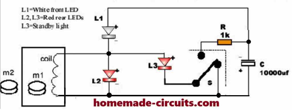
Components & Operation:
- Magnets (m1 & m2): Magnet m2 is mounted on the bicycle wheel. As the wheel turns, m2 causes the tumbling magnet (m1) to rotate.
- Coil & LEDs: The movement of magnet m1 generates electricity in the coil, which powers LEDs L1, L2, and L3 (flashing) while simultaneously charging the 10,000 µF capacitor (C).
Brake & Standby System:
- Paddle Switch (S): Linked directly to the rear wheel brake cable. Applying the brake pulls the cable, pressing the switch's paddle to shift its connection.
- Standby Lighting: Once switched, stored energy from capacitor C discharges through resistor R to illuminate L3 as a standby light when stopped.
For details and full bicycle lighting system setups, visit www.freelights.co.uk.
Key Components and Their Functions
M1 (Tumbling Magnet)
- So we have got this freely tumbling magnet that is hanging out near a coil.
- It tumbles around because of the influence of M2 which is the magnet that is attached to the rotating bicycle wheel.
- This tumbling action is pretty cool because it induces an alternating current in the coil thanks to electromagnetic induction...yes, that’s Faraday's Law at work!
M2 (Magnet on Bicycle Wheel)
- Here we have a fixed magnet that is mounted right on the wheel.
- As the wheel spins M2 interacts with M1 making it tumble and generating electricity in the coil. It is like they are working together to create power!
Coil
- The coil is where the magic happens, it takes the mechanical motion of M1 and turns it into electrical energy.
- This generated electricity is what powers our lights and charges up the capacitor.
L1, L2, L3 (LEDs)
- L1 is our white front light and it is always on whenever the system is generating power.
- Then we have L2 and L3 which are our red rear lights. L3 even acts as a standby light providing some illumination when the bicycle is just hanging out and not moving.
C (10,000µF Capacitor)
- This capacitor is like a little energy storage unit that keeps all the juice generated by the coil.
- It makes sure that the rear lights especially L3 stay lit even when we are not pedaling.
R (1kΩ Resistor)
- The resistor plays a crucial role by controlling how fast the capacitor discharges its energy ensuring we get a steady current flowing to those LEDs.
S (Paddle Switch)
- This switch is connected to the rear brake system of our bicycle.
- When we hit the brakes this switch flips its position and directs stored energy from the capacitor to light up our standby light (L3).
Working Principle
Electricity Generation (While Riding)
- As we ride our bicycle the wheel starts to rotate and M2 makes M1 tumble around.
- That tumbling magnet (M1) generates a current in the coil through electromagnetic induction.
- This current then powers up our front LED (L1) and both of our rear LEDs (L2 and L3).
Charging the Capacitor
- Any extra electricity that gets generated by the coil goes on to charge up the capacitor (C).
- This means we’ are storing energy for when we decide to take a break and stop riding.
Operation When the Bicycle Stops
- If we pull on the brakes then that paddle switch (S) redirects all that stored energy in the capacitor through the resistor (R) to light up our standby LED (L3).
- This way we stay visible even when we' are just stationery and not moving.
Energy Discharge
- The capacitor slowly discharges its energy through the resistor which helps keep that standby light (L3) glowing for a little while after we stop riding.
Advantages
- Energy Utilization: We are harnessing the kinetic energy from riding our bike, a renewable source to generate electricity! How awesome is that?
- Safety: It makes sure our lights stay on (especially that rear standby light) when we stop which helps us be seen at night....safety first!
- Simple Design: There are no batteries or external power sources needed here so it is a super low-maintenance and eco-friendly!
Limitations
- The power output really depends on how fast we are going on our bike, if we are cruising slowly then those lights might not shine as bright.
- The capacitor has a limited storage capacity so that standby light wont stay on forever, it’ will only glow for a short time after we stop.
Basically this whole system is a clever way for us to power bicycle lights using mechanical energy without needing batteries at all... Its sustainable and super practical!



Questions & Answers
Hello Swagatam. And what LEDs are in this circuit?Does the magnet rotate inside the reel or outside in the common body, or near the end of the coil?If possible, then draw a more precise diagram, it can be improved in some way so that the LEDs glow brighter. I will be very grateful to you for everything.
Thank you Andrei,
M1 is the tumbling magnet inside the tube on which the coil is wound, and M2 is the magnet which is fixed on the rim of the cycle wheel.
When the wheel rotates the tumbling magnet tumbles inside the tube on which the coil is wound, while the M2 magnet lines cut the coil externally once on each rotation of the wheel.
Это я понял,но вы не ответили про светодиоды,какие там нужно ставить.
You can refer to this image which is clearer and shows the exact locations of the LEDs:

Hello O Swagatam. My name is Andrei Gaponik, I am fond of soldering interesting schemes. I have a question for you: how is the free energy generator for a bicycle arranged in this scheme, how many turns of the generator coil or what resistance it has, how is the magnet located inside the generator body (at the end of the coil or along the coil).Thank you in advance.
Thank you Andrei,
I think you can experiment with a magnet/coil setup which can be identical to a shake powered flashlight, as explained in the following article:
https://www.homemade-circuits.com/shake-powered-flashlight-circuit/
Здравствуйте Swagatam.В генераторе свободной энергии для велосипеда какая стоит катушка:какой диаметр,из чего сделана:феррит или простое кольцо.Какой диаметр провода и сколько намотано витков.Я буду благодарен вам за ваш ответ.
Hey Andrey,
In this circuit, an air-core coil (or a coil wound on a lightweight plastic/non-magnetic frame) is used so that the magnet m1 can freely tumble inside when driven by the external magnet m2.
Approximate Coil Specifications:
Wire: Enameled copper wire, diameter 0.15 mm – 0.20 mm (32–35 AWG).
Number of turns: Around 1000 – 1500 turns (more turns produce higher voltage at low speeds).
Inner diameter: Must be large enough for the small cylindrical magnet m1 to move and tumble freely inside.
The main requirement is that the coil must not contain ferromagnetic materials (like iron or ferrite). Otherwise, magnet m1 will stick to the core and won’t tumble as the wheel rotates.
Thank you, Swagatam. What can I change in this circuit if I want to install a 1-watt LED on the front light and I have a simple bicycle without a handbrake? How can I further improve this circuit?
You are welcome Andrey! To run a 1W LED, you will need a bit of a buffer because the coil only produces around 20 to 50 mA, which is not enough to drive a 1W LED directly. You can fix this by using Schottky diodes like the 1N5819 to rectify the coil’s AC output and store the energy in a 5.5V supercapacitor, then power the LED from that capacitor. Since you don’t have a handbrake cable to trigger switch S, you can replace it with an automatic PNP transistor switch or a simple vibration sensor so standby LED L3 lights up automatically whenever the wheel stops moving. Finally to boost your power output as much as possible, try using strong N52 neodymium magnets for both m1 and m2.
Thank you, Swagatam, for your reply. Can you draw a complete diagram of what it should look like? I’ll then use this diagram to solder the entire unit together. Thank you so much for your help.
Hi Andrey, sure, i can give you the circuit, but please remember, the 1 watt LED might remain illuminated only for 5 to 10 seconds once you stop paddling, using maybe a 1 or 2 farad super capacitor…is that ok for you?….
Да,устроит.Дайте мне такую схему.Я хочу её на передний фонарик переделать.Пусть и впереди будет свет от магнитов.
The circuit which is presented above does not work in the simulator, and is also difficult to simulate in mind, it seems it’s incorrect somewhere…I will have to design a completely new circuit which will work perfectly, please give me just a couple of days, because currently I am working with some other pending circuit designs…
I will definitely solve it for you day after tomorrow…
Благодарю вас Swagatam!Буду ждать вашу схему.
Hey, Andrey, here’s the circuit that I propose, and should work without any problems, provided the generator coil is designed correctly for optimal power output.
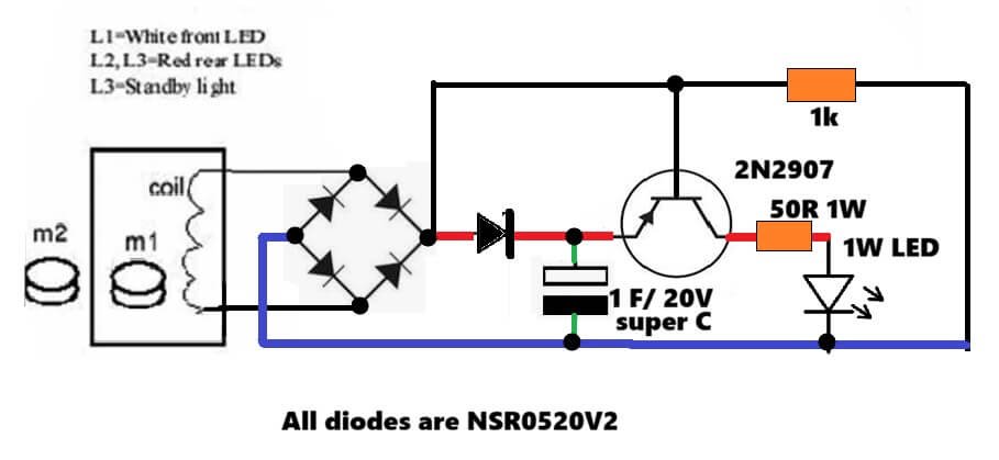
Thank you, Swagatam, for the diagram. You show a 1 F, 20 volt supercapacitor. I have a 2 F, 5.5 volt supercapacitor. Will this one work in this circuit?
Hi Andrey,
The problem is that, if you ride the bicycle fast, then the generator could generate more than 6V or 10V which might cause damage to the capacitor, that is why I suggested a 20V capacitor. However, if you have 2 of these 5.5V capacitors, you can put them in series to make it 11V, which might be ok..