In this post I have explained how a pendulum mechanism can be used for achieving overunity and generate electricity in the form of free energy.
Pendulum Working Principle
We all know and have practically seen how a pendulum works or oscillates. Technically it may be defined as a mechanism made up of a shaft with a weight hanging at its lower end, and the upper end of the shaft being hung over a fixed pivot, such that when the weight is given a manual push, the shaft is forced with a lateral swinging movement wherein the pivotal point experiences a minimum or a zero displacement compared to the weight end which undergoes a maximum relative displacement while the oscillation is in progress.
A pendulum can be considered as one of most efficient mechanisms, just like the lever mechanism which has the potentials to produce a "work" output which may be much higher than the "work" done at the input.
This may be witnessed by the fact that a pendulum is able to sustain a strong swinging action for a very long period even with an insignificant amount of force applied by a manual push on it. The high ratio of input and output work done by a pendulum is achieved due to two external forces acting on the system, namely the gravitational force and the centrifugal force.
The Input Output Work Ratio
The input to output work ratio can be deduced by studying this simple example:
Suppose a pendulum is at rest at the center of its gravity. Let's assume an external push is applied to the pendulum mass such that it is displaced with some angular upward motion to a distance of say 4 inches, however due to the effect of gravity the mass tries to restore its position and in the process the pendulum undergoes an opposite motion until it reaches back to its center of gravity point, but because of the highly reduced friction at the pivotal end, the mass is unable to hold the center of gravity position and is forced to continue with the motion crossing the center of gravity point until it reaches the other extreme end, and the process takes the form of a to and fro oscillation.
Assessing the Hidden Overunity in Pendulum
Let's assume the initial manual force displacing the pendulum is around 4 inches, and then as the pendulum oscillates, we can assume the resultant movements to be the outputs from the pendulum in a slowly decaying fashion from:
0 to 4 (initial push)
then 4 to 0, and then from 0 to 3 at the other end,
then 3 to 0,
then 0 to 2,
then 2 to 0,
then 0 to 1,
and finally 1 to 0 (pendulum stops).
Adding the outputs we find the result to be 4+3+3+2+2+1+1 = 16 in response to a push of 4, this implies an output that's around 4 times more than the input.
Some Formulas and Calculations:
Period of a Pendulum
T = 2π √(L / g)
- T = Period (time for one complete swing)
- L = Length of the pendulum (distance from pivot to center of mass of the ball)
- g = Acceleration due to gravity (approximately 9.8 m/s²)
Force on the Pendulum
F = m × a
- F = Force acting on the pendulum
- m = Mass of the steel ball
- a = Acceleration caused by the shock or movement
Sensitivity of the Spring (Hooke’s Law)
F = k × x
- F = Force applied to the spring
- k = Spring constant (stiffness of the spring)
- x = Displacement of the spring from its equilibrium position
Resonant Frequency of the Spring-Mass System
f = (1 / 2π) √(k / m)
- f = Natural frequency (in Hz)
- k = Spring constant
- m = Mass of the steel ball
Pendulum Drawback
However one drawback of the pendulum is that just like any other mechanism it's too restricted by the first law of thermodynamics, and therefore its swinging action gradually slows down until finally it reaches a halt.
Anyway, here it would be interesting to investigate how the extreme efficiency of the pendulum can be made to do some useful work and also how the oscillations can be sustained permanently by an external trivial amount of force
Achieving Overunity from Pendulum
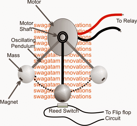
Referring to the image above, the set up shows a pendulum shaft connected with a motor spindle. The pendulum rod has a heavy spherical mass attached with its lower end, the mass has a permanent magnet stuck at its lower edge.
A reed switch can also be seen placed within the central axis of the pendulum mass that crosses its center of gravity, such that while the pendulum is in motion, the magnet on the pendulum mass just "kisses" past the reed switch. Each time this happens the reed switch closes its internal contact momentarily and releases as soon as the pendulum has crossed it.
The motor wires are connected with a relay mechanism, while the reed switch is configured with a flip flop circuit, as may be learned from the following discussion:
How it Works
The objective here is to provide the motor with a clockwise and an anticlockwise instantaneous rotational pushes so that the pendulum swinging action connected with its spindle is sustained permanently.
The motor here acts like a motor and as well as a generator which receives the sustaining pulse from the battery in order to keep the pendulum kicking, and also simultaneously generates the charging electricity for the battery, but at a much higher rate than the pulse rate.
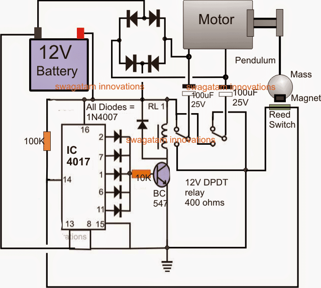
The circuit functioning of the proposed pendulum free energy generator may be understood with the help of the following points:
The IC 4017 forms a simple flip flop circuit which toggles its outputs alternately ON and OFF in response to the pulses from the reed switch at its pin#14.
The alternate ON/OFF switching at the output of the IC triggers the relay driver correspondingly and toggles the DPDT relay on every crossing of the pendulum mass across the reed relay.
The moment the pendulum mass crosses the reed, the reed contacts close causing a trigger pulse at pin#14 of the IC which in turn toggles the relay, the relay flips the connected voltage polarity to the motor such that the pulse complements the clockwise or anticlockwise movement of the pendulum, reinforcing the swinging action of the pendulum by a bit on each of its swinging cycle.
The presence of the two series capacitors with the relay contacts makes sure that the pulse is only momentary and only a factional energy is used for keeping the pendulum swinging.
In the meantime the movement of the pendulum produces enough electricity for keeping the battery charged to a degree where its energy becomes sufficient to be used for powering some other external gadget.


Questions & Answers
Place the reed switch in the trajectory of the calibrated pendulum in such a way that it energizes an electromagnet of opposite polarity to the one that carries the mass, causing an impulse and maintaining the oscillation
Hello Swagatam,
This concept seems brilliant, thanks for publishing your good work. I think the most important thing would be the timing of the short pulses, if they are applied when the pendulum has low velocity to lift the pendulum the gain might be maximised since the pulse has to overcome minimal back EMF in the motor armature at this time. Of course the best time to generate is when the pendulum is swinging with highest velocity at the bottom of the swing which is what you already have here. There is much science could learn from this basic concept, especially about the distance covered, velocity and direction of the pendulum during the time periods of pulse application. The motor generating is more readily understood, this is just a matter of armature EMF overcoming battery EMF when pendulum velocity is highest.
Randal
The pendulum passes at high speed through the lower part of the central axis with the risk of not detecting the reed switch and it would be more convenient to detect it in the upper left or right dead center to apply the pulse to the pendulum motor
Thank you Randal, I appreciate your feedback, and glad you liked the post! Your explanation definitely makes sense. I am sure the readers will find your views interesting.
sr.swagatam si al pendulo por tener una masa magnetica en uno o ambos puntos superiores , colcamos un elctroiman y antes de llegar a este punto un reed suitch para sensar esta posicion activamos el electroiman para rechazar el peso y dar impulso a la masa y continuar su elongacion . A travez de su recorrido se colocaran bobinas recolectoras de energia para cargar las baterias.
Thank you Nelson, that appears to be a good, viable idea.
High Swagatam,
To anybody interested in pendulum energy I offer to visit and study one of the most prominent researchers in the world in Serbia https://www.veljkomilkovic.com/indexEng.htm Veliko has many good concepts and is absolutely open sourced scientist and engineer. Good reading to everyone.
Glarus
Thanks for the information Glarus, I appreciate your feedback!
Hi Swagatam,Thanks for sharing. What if the force that keeps the pendulum swinging comes from a weight using the principle of a cuckoo clock for example. Would the input output work ratio be good enough to charge a battery with a weight of let’s say 1 kilogram? Kind regards, Paulo
Hi Paulo, a cuckoo clock may be having a very weak pendulum, so I don’t think it would have sufficient strength to sustain a 1kg pendulum.
Hi Swagatam, Thanks for your reply. I agree that the cuckoo clock has a weak pendulum. However the weight that keeps the pendulum in motion is much heavier (1kg for instance) and easily sustained by the clock. So my question is if I could use the cuckoo clock’s concept in order to charge a battery!? Kind regards, Thilo
Hi Paulo, if the existing weight is near 1 kg then I think it may work to sustain the oscillations as well as power the battery, just like a Bedini motor.
Thanks, I’ll take a look.
Hi Swag,
That was new to me and I downloaded their white paper. They continuously speak of higher efficiency and better power for less input torque in these generators. Nowhere do they speak of over-unity. Over-unity simply means an efficiency of 100% plus. Nothing less. What their tech does is to address the inherent resistances of the mechanical construction, the magnetic properties and their inherent resistances and so on in the VRM.
http://www.flynnresearch.net/technology/PPMT%20Technology.htm
Very good development, very good tech. Brilliant really.
This is where my nitpicking comes in. The Prof (Dean of Applied Math here those years) laughed at us many times when we failed to look close enough. This happened especially in the study of pendula. Some really awesome differential calculus in the mathematical description of that movement. First problem comes in between the knife edge fulcrum of the pendulum and the high radius support. However; this is the first thing we had to understand. The support, without which the pendulum will not swing, is EXTERNAL to the pendulum. An electron microscope will show the almost immediate deterioration in the knife edge. The rounded edge immediately loses efficiency.
This causes the construction of the grandfather clock. It has a spring and an escape mechanism to KEEP the AMPLITUDE of the clock’s pendulum exactly the same to mark time.
Any load is a resistance to a motor, these included. Get two of these PPMT devices and connect their shafts directly to avoid other issues. The first is the driver powered by an electric current. The second is a current generator against a load. Check the output current against the input current. Anything in between those points is INTERNAL to that mechanism. Second law of thermodynamics.. Then switch off the driving current to the first device. Ten million dollars the whole thing will wind down to a stop. The second generator device introduces drag to the first similar to that in the VRM.
Humans have elastic collisions with Earth. Rubber balls have non-elastic collisions (almost) with Earth. They lose potential energy (height) and gain kinetic energy (speed). Then, in the collision, the kinetic energy is lost through the deflection in the ball. The second and later bounces are lower than the initial point of release of the ball. Soccer balls do what they do because there is just about no energy lost through deformation.
In studies on momentum they use chromium steel balls to exclude elasticity in those bodies. They have, as far as I know, not yet achieved 100% non-elasticity. The deflection is microscopic, but definitely there.
The trick is to decide on the boundaries of the system – any system – before you can talk about over or under unity.
Hi Christo i appreciate your response, here the concept is a hypothetical condition. Here we are trying to take the advantage of the special configuration of the pendulum which is able to sustain its kinetic energy with extraordinary efficiency and allows us to use it back for doing a work.
Here we are assuming that the effort required to initiate the swing on a pendulum is much larger, but to sustain the swinging is much smaller. If this swing is maintained with a small external energy, an output equivalent to the initial effort could be constantly derived from the sustained swinging of the pendulum.
My expertise is in the field of electronic circuits, not much in physics at the moment, although I used to be a great fan of physics which gradually was replaced with electronic circuit theories.
Swag,
Accepted. I was really correcting myself. It was only after I understood the effect of inertia on the swing arm that I could solve these math tutorial problems. The effect is that the swing arm is under tension. These tension forces are shown in diagrams as two arrows pointing towards each other.
Similar to the discussion on conventional current indication (positive to negative) and real current indication (negative to positive).
I’m just not convinced of over-unity. Energy cannot be created or destroyed. Not even Tesla found a way past that. As you said in another post that you have to have a supply voltage on the amplified side of a transistor. Amplification does not exist in fact. You can only modulate a 600 Volt supply by, say, a 0.5 Volt signal through the transient resistance of a transistor. You cannot change the 0.5 volt itself into 600 Volts.
I’ve written this more for the people who are starting new careers or interests in this fascinating field.
Then I apologize if anyone got the idea that I may have wanted to create some contention. That was not my idea.
Regards,
Christo.
Thanks Christo,
In the pendulum theory, we lift and release the pendulum only once but it keeps swinging to and fro many times giving an impression of an outcome which may be much higher than the initial lifting force. When we humans jump and land on ground we do not bounce back upwards but a rubber ball does because of its inherent property, such phenomenon seems to be producing excess energy than the input, the driving factor here is the earth’s gravitational force which causes the pendulum or the rubber ball to keep oscillating. Similarly in parallel path technology the magnetic force is the driving factor, which causes the extra energy to develop.
Gents,
I think I can contribute something here. In Applied Math II we had the wake up call that there is no such thing as centrifugal (centre-flying) force. There is another force called centripetal force (centre-seeking) force. The effect that makes the weight appear to fly away is inertia. This is simply the quality of bodies to remain in the current state. Moving or stationary. The weight wants to move in a straight line (inertia), but the centripetal force in the pendulum arm keeps it rotating around the centre. This conflict plus the effect of gravity plus! the effect of wind resistance are the causes of the observed entropy.
This is the real reason why over-unity or perpetual motion is not possible on this planet. Friction or resistance of whatever form is the sole most important cause of this.
According to what Swag says about electricity just above your head, it seems to be possible. Tesla, Moray and the towers, pyramids. The most surprising thing I learned in theory is that EVERYTHING in relation to anything else forms a capacitance pair. Reason for the armband at your electronics workbench. Same as shorting the leads on a capacitor.
However; one has to be very careful not to divide by zero. That is a concept in math, but one can theorize like that as well. You need to define very clearly what you are working with, what result you get and WHY you are getting that result.
Thank you Christo, that’s very enlightening…we appreciate your knowledge…keep posting mate!
Swag,
Thanks. This is the kind of thing that inspires me. I share it to encourage others to look deeper, to find out more. The Universe truly is a wonderful place.
Correctly it is not the weight that wants to keep moving in a straight line, it is the mass. Mass is the measure of the inertia of a body.
So a very high speed spaceship has very high inertia and cannot turn very quickly, but that’s something for Einstein.
Weight is the measure of gravitational pull on a body.
Thanks Christo, I used weight as the general term because we normally associate weight as the factor which affects the actions of a body on the surface of the earth. Mass should be the correct technical term.
Someone build this device?
hey. i need to model this pendulum Generator in matlab.
can you provide me the physics equation please?
Xavier, the pendulum size and dimension will need to be to matched with the load current, and there's no restriction to it…… if you use a smaller pendulum for a relatively heavier load then it won't be efficient.
and here we not interested to short the motor output rather use a calculated amount of power for charging the battery, and a small surplus power to kick back the pendulum
Swagatam,
You cannot assume that the pendulum is a "highly efficient mechanism" when you are using it to charge the battery.The motor itself will offer resistance to the pendulum's movement. Just check the difference when you try to turn a motor spindle with its wires shorted and when the wires are free.
Well, Swagatam,is your pendulum still running?
Appreciate the effort you put into this site.
Yup, should work but replace relays with mosfets, cheap and very high current ratings – TO220 TO 20 AMPS, quickly, high energy, short duration pulse to the motor which will kick ass! 1mS kick should be
Hello Swagatam,
Are you saying that in the final analysis , the battery never runs down?
This looks very similar to the circuits used in electronic clocks, but their batteries eventually run down.
Thanks Swagatam
Hi Jade, any 1 amp rated reed will do
hello swagatam,
What's the specifications of the reed swith?
Hi Chinmoy, the power from the pendulum is not dependent on it's speed rather the force, which in turn is dependent on the hanging mass, and the efficiency depends on the pendulum rod length. Heavier mass will allow heavier generators to be incorporated for generating higher magnitudes of current, and a longer connecting rod will allow more number of oscillations to persist
the relay current can be assumed to be negligible if the battery and the motor are much heavier compared to the relay specs, however if anybody wants to save that extra bit of power, he can simply replace the relays with an H-bridge stage.
Pendulum is a highly efficient mechanism so it's definitely not absurd to imagine that it cannot work in the manner proposed by me.
the only aspect that needs to be calculated is the amount of current required for the short pulse that would enable the pendulum to recover the small amount of loss it's supposed to lose in the course of its oscillation.
If possible I try to put forth a straightforward calculation regarding how a pendulum may be capable of providing more output work than the input work
Hi Swagatam
The concept is interesting, but there is a problem. I don't think that a slowly swinging pendulum can provide enough rotational acceleration to the motor to provide sufficient voltage and current for charging a battery. Moreover, the relays get energized with every swing of the pendulum, and electromechanical relays require quite a bit of power to operate, and this power is also derived from the battery. So it is absurd to think that the total amount of power the battery is getting from the motor is more than the total power the battery discharges to drive the relay, the motor and the electronic circuit. I hope I am making sense. Anyway, I would like to know your comments on this.
Thanks and regards.
Hi Xavier, yes I am hoping so, in fact it's supposed to produce excess power which may be used for operating other external equipment.
In clocks the pendulum is never used like a generator, and the cell is never configured to derive charging current from the pendulum, so it may not be a relevant example.
sir what is the voltage deffenent in 10uf 25v and 100uf 25v . and how to calculate it.
Amit, Chiranjit.
As I understand them their capacitances are expressed in pF, μF and so on. Their maximum voltage ratings are expressed as 5V, 22V, 60V or however they are designed to work. So you can use a 470μF 60V cap in a 470μF 20V circuit, but then there are other issues to consider. That may just affect your circuit adversely.
Swag has whole pages devoted to capacitors. I am sure you will find your answers if you search the site a bit.
Finding these answers will enable you to design more flexibly. In doing this you will see that you are your own best teachers.
Regards,
Christo.
Thank you very much Christo!
I have a same question.. Amit
sorry, I could not understand your question…..?