• Skip to main content
  • Skip to primary sidebar

Homemade Circuit Projects

Get free circuit help 24/7

New Projects | Privacy Policy | About us | Contact | Disclaimer | Copyright | Videos | Circuits for Beginners | Basic Circuits | Hobby Projects | Transistor Circuits | LED Drivers 

You are here: Home / Car and Motorcycle / Free Energy Bicycle Generator Circuit

Free Energy Bicycle Generator Circuit

Last Updated on June 17, 2019 by Swagatam Leave a Comment

caution electricity can be dangerous

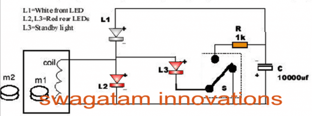
The following post describes a simple circuit idea which can be used for generating free electrical energy for illuminating a few safety flashing LEDs on a  Bicycle.

The Circuit Concept

A bicycle like any other modern vehicle needs provision of lighting system for its use at night or cycling in lesser light. Usually a bicycle is designed with the front light and the back light, being red in colour. The front light is often fitted with a cycle using a dynamo system.

A dynamo generates alternating current by causing a friction in the tyre.

This actually slows down the speed and the cyclist has to paddle with more power to generate speed. Another kind of lighting can run through battery which is usually a detachable device.

But what if a situation when there is no need of dynamo, neither depending on battery for a bicycle light?

The introduction of an innovative system called ‘Safety Flashing Light’ has solved the purpose.

It not only helps to eradicate the concept of battery or dynamo system; it indeed offers more powerful light and longer standby compared to the other types.

This new electrical generating system has already created a sparkle in the bicycle market for its efficiency and ease-of-use.

How the Free Energy Bicycle Generator with Safety Flashing Light Works?

The Safety Flashing Light is designed in a way to handle all possible situations when driving a bicycle. For instance, a cycle when running in slower speed; two white-front LEDs and three red-rear LEDs flashes to make others notice on its presence.

In the case of standby mode, when the rear-wheel break is applied, the front and back LEDs gets activated. The lights are very bright and it can be noticed even in daylight.

Even no maintenance is needed, which made the operation hassle-free and easier to operate. The Safety Flash Light also works perfectly even on a rainy day.

This light system uses 8000-12000mcd LEDs for an optimum performance.

By: Dhrubajyot​i Biswas

Circuit Diagram

You'll also like:

  • 1.  High Voltage, High Current DC Regulator Circuit
  • 2.  Make this Gravity LED Lamp Circuit
  • 3.  Battery Charger for Positive Earth Cars
  • 4.  CDI Tester Circuit for Automobiles
  • 5.  How to Make Car LED Bulb Circuit
  • 6.  How to Connect Car LED Downlight

About Swagatam

I am an electronic engineer (dipIETE ), hobbyist, inventor, schematic/PCB designer, manufacturer. I am also the founder of the website: https://www.homemade-circuits.com/, where I love sharing my innovative circuit ideas and tutorials.
If you have any circuit related query, you may interact through comments, I'll be most happy to help!

Reader Interactions

Have Questions? Please post your comments below for quick replies! Comments should be related to the above artcile Cancel reply

Your email address will not be published. Required fields are marked *

Primary Sidebar

Calculators

  • 3-Phase Power (15)
  • 324 IC Circuits (19)
  • 4017 IC Circuits (52)
  • 4060 IC Circuits (25)
  • 555 IC Circuits (98)
  • 741 IC Circuits (19)
  • Arduino Engineering Projects (83)
  • Audio and Amplifier Projects (114)
  • Battery Chargers (82)
  • Car and Motorcycle (94)
  • Datasheets (46)
  • Decorative Lighting (Diwali, Christmas) (33)
  • Electronic Components (100)
  • Electronic Devices and Circuit Theory (36)
  • Electronics Tutorial (116)
  • Fish Aquarium (5)
  • Free Energy (34)
  • Fun Projects (13)
  • GSM Projects (9)
  • Health Related (20)
  • Heater Controllers (29)
  • Home Electrical Circuits (102)
  • How to Articles (20)
  • Incubator Related (6)
  • Industrial Electronics (28)
  • Infrared (IR) (40)
  • Inverter Circuits (98)
  • Laser Projects (12)
  • LED and Light Effect (93)
  • LM317/LM338 (21)
  • LM3915 IC (25)
  • Meters and Testers (65)
  • Mini Projects (148)
  • Motor Controller (67)
  • MPPT (7)
  • Oscillator Circuits (26)
  • PIR (Passive Infrared) (8)
  • Power Electronics (34)
  • Power Supply Circuits (77)
  • Radio Circuits (10)
  • Remote Control (48)
  • Security and Alarm (61)
  • Sensors and Detectors (120)
  • SG3525 IC (5)
  • Simple Circuits (75)
  • SMPS (29)
  • Solar Controllers (60)
  • Timer and Delay Relay (53)
  • TL494 IC (5)
  • Transformerless Power Supply (8)
  • Transmitter Circuits (40)
  • Ultrasonic Projects (16)
  • Water Level Controller (45)

Calculators

  • AWG to Millimeter Converter
  • Battery Back up Time Calculator
  • Capacitance Reactance Calculator
  • IC 555 Astable Calculator
  • IC 555 Monostable Calculator
  • Inductance Calculator
  • LC Resonance Calculator
  • LM317, LM338, LM396 Calculator
  • Ohm’s Law Calculator
  • Phase Angle Phase Shift Calculator
  • Power Factor (PF) Calculator
  • Reactance Calculator
  • Small Signal Transistor(BJT) and Diode Quick Datasheet
  • Transistor Astable Calculator
  • Transistor base Resistor Calculator
  • Voltage Divider Calculator
  • Wire Current Calculator
  • Zener Diode Calculator

© 2023 · Swagatam Innovations