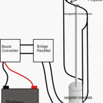
A free energy collector circuit helps to convert surrounding radio frequency waves to electric power and can provide 40 watts to 10 watts indefinitely.
The Circuit Concept
An option to increase the output power is achievable through proper set-up of an antenna. Placing an antenna in a close proximity of a large metal object helps generate additional power.
The wire of an antenna should be more than 150 feet long, which has to be placed horizontally on a higher platform to derive the best result.
The more the higher an antenna is set, the more it is able to act efficiently. However it is advisable to keep the circuit closer to an antenna.
The proposed free energy collector circuit on the other hand, also acts as a passive detector. As the large metal object passes wave, there is an increase in power. One major usage of this process is in the field of volcanic studies.
Selecting the Antenna
The sensitivity of an antenna is capable to detect variation of energy from earth and is often used to receive warning signal for a possible seismic activity.
So it can be summed up that the placement of an antenna is very much crucial for a better output. Also one can use many of these circuits to construct and connect their inputs together, to produce ample energy to run electricity in a house. However to note, each unit needs their own antenna to construct the same.
The Radio Frequency power varies based upon a location. If the set-up location is close to a city or in close proximity to the transmitters, which generates high level of Radio Frequency; leads to an optimal performance.
If you are excited to generate free power at your house from the atmosphere, then you can perform some experiment with different length and size of an antenna.
Altitude is Crucial
However keep in mind to place the antenna on a higher location for better result. During construction it is also necessary to keep in mind the earth ground of the circuit has to be properly conductive. The earth ground should also consist of metallic, conductive pipe or rod.
More Free Energy Circuits can be found in the following link:
Free Energy Devices you can build at home
Submitted by: Dhrubajyoti Biswas
Circuit Diagram
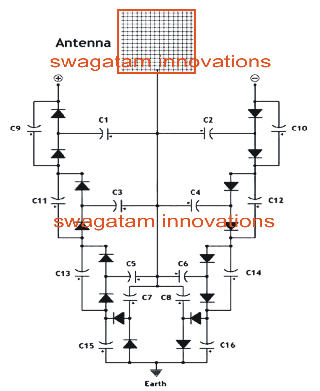
Parts List
All Diodes are 1N4148
C1---C8 = 0.22uF/100V mylar
C9----C16 = 33uF/25V electrolytic
Improving the Free Energy Device
The following more comprehensive free energy deriving circuit design was forwarded to me by one of interested readers of this blog Mr.Prashanth Dhonde.
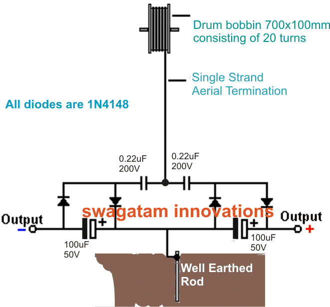
More info on the above design:
Using Fast Recovery Diodes
In order to generate more electricity, it is possible by stepping up with more diodes. To make it work properly, the type of diodes and the construction of antenna play a crucial role.
To begin with this process, let us first start setting up the antenna. In order to set an antenna properly, there are some key issues to consider.
An antenna should be made of Ferrite and a height of 30 inch rod is an ideal option to setup the antenna for receiving radio waves.
In regard to diodes, the Geranium the lowest loss diodes and a low breakdown junction voltage of ~ 0.2 - 0.4 Volts is ideal, in case you are unable to find the you may use the regular 1N4148, would just work.
A radio wave gets intercepted in areas with higher concentration and traffic congestion. In this kind of situation it is seen that each diode can pull around 30mV.

Questions & Answers
TODAY I READ THE ARTICLE. AFTER EXPERIMENT POSSIBLE HOPEFUL RESULTS I COMMENT. MY AREA OF STUDY IS ELECTRONICS AND MATERIAL SCIENCE FOR FORTY YEARS. AFTER RETIREMENT FROM COLLEGE SERVICES I DECIDED FOCUS ON SUCH EXPERIMENTS.
very good. I like this. hopefully we will see this as standard and escape from the fossil fuels and nuclear power plants.
Thank you very much for your useful feedback.
where’s your podcast? seriously, get on that. visuals. we like and NEED visuals. show us.
In the article: “In order to generate more electricity, it is possible by stepping up with more diodes.” An interesting article, but for anyone thinking they can get more power by using more diodes, that is wrong. The amount of power at the antenna is a value dictated by the antenna and the radio stations in the area. It is not related to how it is detected. By adding more diodes, what you are doing is increasing the output voltage using what are basically diode voltage doublers. However, every time you double the voltage, you halve the the output current current. So, it makes sense if you need a particular charging voltage but it will them tale longer to charge. Also, adding more diodes means there is an increased total voltage drop used up by the diodes so you won’t actually get exactly 2x voltage but slightly less and slightly less current as the diode effectively uses up the current. The more diodes, the greater the voltage, but the lower the current and the available output power.
yes .this is the true. As a hamradio operator I make this experiment long time ago ,and even vith a high power longwave broadcast station near me and my 80m longwire can’t detect hf frecvency that can lighting a 3.5 v/50ma bulb,also to measure an rf field from an 100w radiating antena I mus put my simple detector antena using a diode and a 30mA instrument no more than 2-3 mm distans.
Thanks for your valuable feedback, I agree with you.
with cincoG & beyond, is this gonna hijack our options? “space force”
Does it matter what region the antenna is in? or if you perhaps use a hillside instead of an antenna? Start near a creek or use a tree?
Yes, the longer and higher the antenna the better as well as a good earth. This isn’t generating energy form the earth, but from the various transmitters in your area. If you live on an area with lots of powerful transmitters then you will generate more power. If you live in an area where you can hardly pick up any radio stations, you are out of luck. Also, as this is an untuned antenna, you will find the power varying through the day and even the year, depending on local conditions, in the same way as some stations become stronger at certan times of the day.
What is the best antenna to receive 30 volts? I made different circuits, but it does not output more than 1.5 volts. Please guide me to make a better antenna. Thanks
A long wire as high up as possible is the way to go as well as a really good earth. Other aerial designs are more efficient but that is because they are designed to work at certain frequencies. If you have a local radio station that you know is powerful and at a particular frequency, you could tune in to that specifically using either a simple crystal set circuit or a specially designed antenna, Is it worth the effort or cost? You decide!
A specially designed antenna would just be the length that corresponds to the radio station tuning frequency, correct? (Using the c constant formula for speed of light.)
In need your help with your project
Hi Swagatam
i posted a question which was deleted, is there something wrong with the question, sorry if it the case
Bests regards
Gironimo
Hi Gironimo, which question are you referring to?
Hi Swagatam
The question December 15, 2021 at 10:51 pm(4 digital state ++ +- -+ — on) , i thought it was deleted as its unrelated to the original subject (free energy)
thks for your reply
It was not deleted, you can check it under the article, but yes posting comment under unrelated post may not be good for the site!
hi Swagatam
I have a question, what is the meaning of 4 digital state ++ +- -+ — on off do this do that …..in a circuit of leds(info from of an engineer ) i always do with 0 and 1 using and nor xor gates but with plus and minus i don’t understand if its the same thing
Thks in advance
Gironimo
Hello! Let me explain something to you. leave the circuit aside and take only the long wire antenna. This will capture electricity from electromagnetic waves of positive value and another wire that you will take from a grounding will give you negative electrical charges. Put a measuring device between them and you will see how many volts it gives you. For more volts, you will increase the length of the wire.
Hi Geronimo,
Sorry, I have no idea about it. Can’t figure it out!
Hi Swagatam
if it can help i built one yesterday
and i got up to 40 volts using just two MKP-X2 220N and 4 diode germanium 1n
the current is too weak about 0.026A at the out of a capacitor,
1.My question is how to increase current.without adding more Cap and Diode (i know that to increase current i can increase current)
2. which capacitor y advice me to wire with the circuit to charge quickly voltage
Thks in advance
Thank you Gironimo for updating the results, it looks very encouraging.
However, unfortunately, increasing the current may not be possible unless more number units are added in parallel.
Thank y Swagatam i forgot to notice that
Antenna i m using is coaxial used for Tv installed on the roof of the building at about 15 Meters
Sincerly
No problem Gironimo, thanks for updating the information!
Mi comentario seria una casa seria abastecida por este sistema de energia libre ,y no depender de las grandes monopolios de la energia caliente que nos venden
hello everyone where can i buy this kit. Can anyone make it for me?
What happens if the power grid fails
Instead of the drum bobbin, can we use lightning arrestor rod or old wireless receiver antenna. kindly let me know.
The drum bobbin is air cored according to me, so iron or ferrite cored bobbins will not work
Hello
I need a good free energy circuit to charge a LiFePO4 leisure battery in my RV. Can you help me?Thanks
Why not just power a joule ringer and use the coil to run a second transformer to run an op amp to up the voltage and drive an avalanche transistor as a current source at high voltage?
Hello,
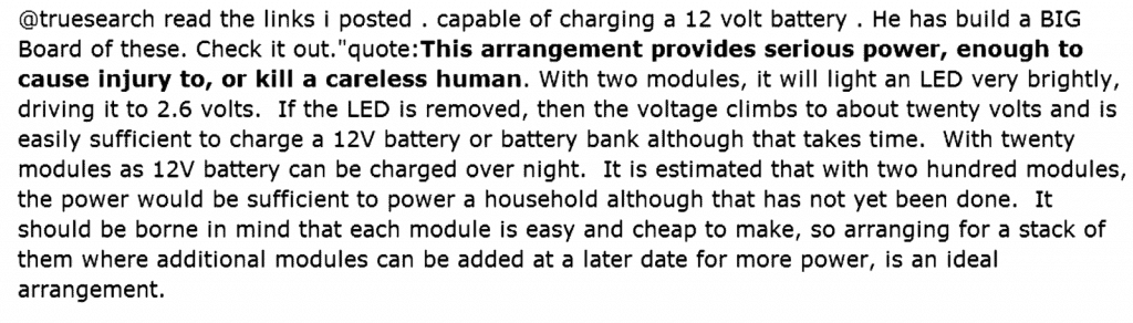
wonderful ideas here! But the schematic under “Using Fast Recovery Diodes” shows the groups of 5 diodes are facing each other and not in series. Can you explain how that works? Also, how many turns of what size wire is over the 30″ ferrite rod?
Thank you in advance for your answer,
Sincerely,
Steve
Hi thanks, yes the diodes seem to be connected with cathode to cathode in series, which will simply not allow any current flow. I took the pics from one of the free energy forums, so have no idea regarding the working concept behind this configuration.
Sir,
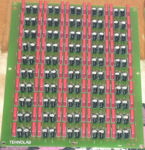
Concerning the “How to Collect Free Energy from Atmosphere” I would like to built several pcb(Dragan Kljajic) but I have not the scaled printed circuit picture. I got one pcb drawing but not in proper size that would fit the components.
Could you please send me the PCB picture if you have it.
Thanking you in advance
I can help You !
zszabo@freemail.hu
Hi Hasan,
I am really sorry, making the PCB design can be difficult due to lack of time…I wish I could do it for you!
Hello Swagatam. Please May I have a circuit designed by you which I can integrate with readymade NE555 Module to properly drive IRF9540N which is a P-Channel Mosfet I plan to you to Drive an Inductor and do further test on?
My input voltage will be between 24V to 36V.
Please your help is Needed.
Hello Dare, please specify what exactly you are trying to implement, I will try to help!
Very low forward voltage drop diode is 1N5817 I think they are more efficient than diodes with germanium 1n34 !
Thank you for your fast reply. I have another question if I can , after the fourth (last)turn to the second row the wiring changes why? This is regarding the geranium diodes schematic.
Thanks Jim
There’s no change in the coil, it’s uniform from start to end.
In your geranium diode diagram is the antenna 30” (ferrite) long? How many turns should I use?Have you or any of your followers made this ,and what was there out put voltage?
Thanks Jim
It’s between 300 to 1000 turns of 30 SWG wire.
I haven’t tested it yet!
Hello swagatam, kindly look at d video in d link below and advice if it could work.
Regards
Hello Stanley, that’s a super FAKE video, will never work. The scene was paused and changed twice, that clearly shows the set up was manipulated.