• Skip to main content
  • Skip to primary sidebar

Homemade Circuit Projects

Need circuit help? Post them in the comments! I've answered over 50,000!

Blog | Categories | About | Hire Me | Contact | Calculators-online
You are here: Home / Datasheets and Components / Understanding Color Codes of Resistors with Practical Examples

Understanding Color Codes of Resistors with Practical Examples

Last Updated on May 17, 2026 by Swagatam 2 Comments

In this post I will comprehensively explain regarding the various standard resistor color codes, and systems employed for assigning resistors their specific values. The post also explains how to read and identify resistor values from their color codes.

Table of Contents
  • Basics of the color codes used in Resistors
    • Color code scheme of resistors consisting of four bands
    • Color code scheme of resistors consisting of five bands
    • Color code scheme of resistors consisting of six bands
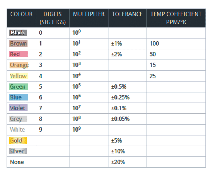
    • Color Code Chart for the Resistors
    •  

By: S. Prakash

The color codes used in resistors denote a leaded resistor’s value. These color codes of resistors have been used for a long time now.

The color code system used for the resistors is one of the most reliable and easiest methods for indicating the value.

This is true because at many occasions it has been observed that the values which are printed on the resistors are erased or obscured while transfer and handling of the resistors and thus identifying the values become difficult.

Basics of the color codes used in Resistors

The color coding on a resistor is done on the rings which the resistor has placed around itself and are colored.

The printing of figures or numbers on the resistor becomes difficult since all the leaded resistors are virtually of cylindrical shape.

Also, as discussed above, the usage and handling of the resistors can eliminate or obscure the prints.

In case, the coding scheme of the resistor is partially marked, the various rings present around it on which the color coding is dependent enables the deciphering of the various information related to the parameters and the values of the resistor.

The color coding systems which can be applied on a resistor is decided by the accuracy and the tolerance level which the resistor requires.

The color code systems used in various different resistors can be observed to be based on the same outline but the information which is provided by them is of different levels.

The major color coding systems which can be observed on a resistor are:

  • Color code scheme of resistors consisting of four bands
  • Color code scheme of resistors consisting of five bands
  • Color code scheme of resistors consisting of six bands

The color code scheme in the resistors is provided on the basis of the number of rings which are being used by the resistor.

Color code scheme of resistors consisting of four bands

The series values for which the color code scheme of four bands is used are E24, E6, and E12 respectively.

The significant values which can be accommodated in this can range up to two figures.

The resistor accepts the values which are in range of maximum E24 along with the tolerance vale which is being accommodated by the resistor is in a maximum range of ±2%.

The color code scheme of the four bands of resistor provides information regarding various parameters of the resistors such as the temperature coefficient, value, and tolerance level.

The name given to the band which is located closest to the resistor’s end body is “Band 1”. Out of the four bands, the resistor’s value’s significant figures are represented by the first two bands; while the multiplier is represented by the color code of the third band placed on the resistor.
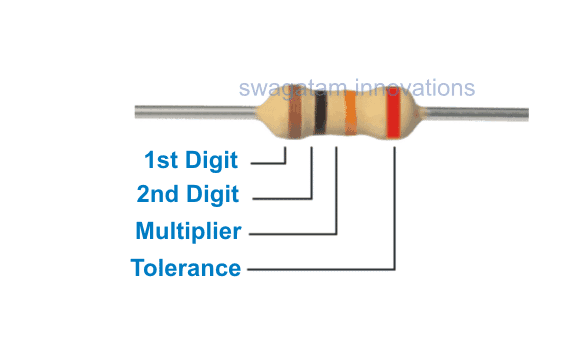
Color code scheme of resistors consisting of four bands

For example the color code scheme present on the above shown resistor consists of colors red, black, and orange along with a red band at the right side as the fourth band.

The first two color bands namely red and orange represent the significant figures of the resistor’s values which is 10; while the third color band orange represents the multiplier which is 1000.

The fourth color band which is red represents the tolerance level of the resistor which is ±2%. Thus, the value of the resistor can be interpreted to be 10,000Ω or 10kΩ.

Note: In case a resistor consists of only three color bands, then the first two bands will represent the significant figures of the resistor’s values while the third will represent the multiplier. The fourth color band representing tolerance will be absent here.

Color code scheme of resistors consisting of five bands

The color code scheme of resistors consisting of five bands is used for the series E192, E48, and E96 since these resistors require high tolerance levels which are in the range of ±1%.

Thus, in order to represent the significant figures of the resistor’s value, three bands are required and thus one extra band can be observed in this case. In all other sense, the color code scheme of resistors consisting of five bands is similar to that of the four bands only.
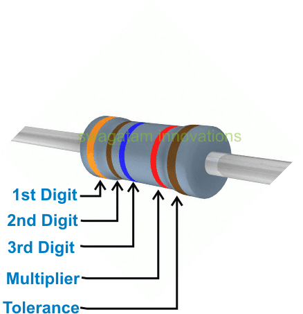
Understanding Color code scheme of resistors consisting of five bands

For example, the color bands present on the above resistor are orange, brown, blue, red, and brown.

The first three color bands represent the significant figures of the resistor’s value which is 316; and the fourth color band represents the multiplier of the resistor which is 100.

The fifth color band of the resistor represents its tolerance value which is ±1%. Thus, the value of the resistor can be written as 31.6kΩ or 31600Ω.

Color code scheme of resistors consisting of six bands

The color code scheme of resistors consisting of six bands provides the maximum level of information regarding the parameters of the resistor.

The series for which the color code scheme of resistors consisting of six bands is used are E192, E$*, and E96 respectively.

The color code scheme of six bands is used for the resistors which has tolerance values which are very high and in the range of ±1%.
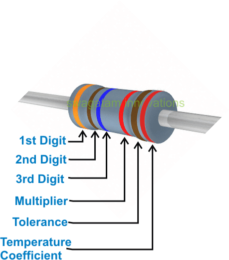
Color code scheme of resistors consisting of six bands

An example of the color code scheme of resistors consisting of six bands is shown above wherein the six colors on a resistor are orange, brown, blue, red, brown, and red.

The first three color bands present on the resistor represent the significant figures of the resistor’s value which is 316 while the fourth color band represents the multiplier which is 100.

The fifth color band represents the tolerance level of the resistor which is 1%. The sixth and the final color band represent the temperature coefficient of the resistor which is 50ppm/ºK.

Thus, the value of the resistor can be written as 31.6kΩ or 31600.

Color Code Chart for the Resistors
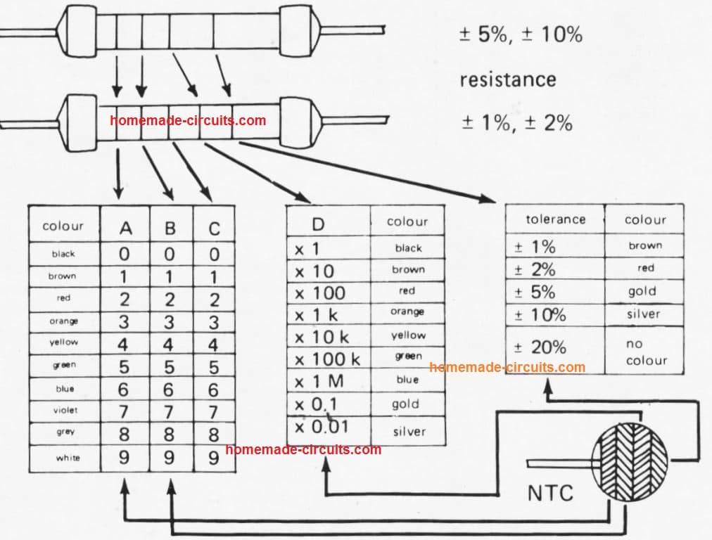
resistor color code chart


All types of leaded resistors which has approximately one watt of dissipation levels of power uses a color code.

Apart from this, the size of the resistors is sufficiently large and constructed accordingly in order to mark the various values and parameters in figures.

Thus, the leaded resistors widely use the colour code scheme. The color coding scheme of the capacitors is also based on basics of similar concept.

You'll also like:

  • hometheaterictda7560IC TDA 7560 Datasheet – 4 x 45W QUAD BRIDGE CAR RADIO AMPLIFIER PLUS HSD
  • LM324 Operational AmplifierLM324 Quick Datasheet and Application Circuits
  • 2N3906 pinout details2N3906 Datasheet [40V, 200 mA, PNP Transistor]
  • pindetailsArduino LCD KeyPad Shield (SKU: DFR0009) Datasheet

Filed Under: Datasheets and Components Tagged With: Codes, Color, Examples, Practical, Resistors, Understanding

About Swagatam

I am an electronics engineer and doing practical hands-on work from more than 15 years now. Building real circuits, testing them and also making PCB layouts by myself. I really love doing all these things like inventing something new, designing electronics and also helping other people like hobby guys who want to make their own cool circuits at home.

And that is the main reason why I started this website homemade-circuits.com, to share different types of circuit ideas..

If you are having any kind of doubt or question related to circuits then just write down your question in the comment box below, I am like always checking, so I guarantee I will reply you for sure!

Previous Post: « How Flex Resistors Work and how to Interface it with Arduino for Practical Implementation
Next Post: Types of Capacitors Explained »

Reader Interactions

Questions & Answers

Total Posts: 2
Newest Oldest
Sherwin Baptista
January 9, 2018 • 9 years ago #57504

Dear sir,
I have two 1E/1W resistors. If i place both resistors in series i get 2E, here what happens to the wattage does it remain 1W or it changes,
similarly if i connected both in parallel i get 0.5E, here do i still have a 1W or is it different?

Reply
SwagatamAdmin
January 10, 2018 • 9 years ago #57516

Dear Sherwin,

In series connection the resistors will show no change in their wattage, but in parallel their wattage will add up.

Reply

Need Help? Please Leave a Comment! We value your input—Kindly keep it relevant to the above topic! Cancel reply

Your email address will not be published. Required fields are marked *

Primary Sidebar

My YouTube Channel

Circuit Simulator: Draw and Simulate Schematics

circuit simulator image

Categories

  • Arduino Projects (95)
  • Audio and Amplifier Projects (134)
  • Automation Projects (18)
  • Automobile Electronics (104)
  • Battery Charger Circuits (90)
  • Datasheets and Components (109)
  • Electronics Theory (151)
  • Energy from Magnets and Earth (43)
  • Games and Sports Projects (11)
  • Grid and 3-Phase (20)
  • Health related Projects (27)
  • Home Electrical Circuits (13)
  • Indicator Circuits (16)
  • Inverter Circuits (98)
  • Lamps and Lights (161)
  • Meters and Testers (72)
  • Mini Projects (28)
  • Motor Controller (68)
  • Oscillator Circuits (30)
  • Pets and Pests (15)
  • Power Supply Circuits (91)
  • Remote Control Circuits (50)
  • Security and Alarm (65)
  • Sensors and Detectors (107)
  • SMPS and Converters (46)
  • Solar Controller Circuits (62)
  • Temperature Controllers (44)
  • Timer and Delay Relay (51)
  • Voltage Control and Protection (44)
  • Water Controller (37)
  • Wireless Circuits (31)

Subscribe to get New Circuits in your Email

Other Links

  • Privacy Policy
  • Cookie Policy
  • Disclaimer
  • Copyright
  • Videos
  • Sitemap

People also Search

555 Circuits | 741 Circuits | LM324 Circuits | LM338 Circuits | 4017 Circuits | Ultrasonic Projects | SMPS Projects | Christmas Projects | MOSFETs | Radio Circuits | Laser Circuits | PIR Projects |

Recent Comments

  • Swagatam on 24V to 12V DC Converter Circuit [using Switching Regulator]
  • Swagatam on Automatic Battery Full Cut-Off Latching Circuit with Trickle Charging
  • Ramin on Automatic Battery Full Cut-Off Latching Circuit with Trickle Charging
  • Joss on 24V to 12V DC Converter Circuit [using Switching Regulator]
  • Swagatam on Simple Capacitive Discharge Ignition (CDI) Circuit

Social Profiles

  • Twitter
  • YouTube
  • Instagram
  • Pinterest
  • My Facebook-Page
  • Stack Exchange
  • Linkedin

Calculators

  • ZVS Induction Heater + Tank Calculator Tool
  • Zener Diode Calculator
  • Wire Current and Thickness Calculator (Ampacity Calculator)
  • Voltage Divider Calculator
  • Transistor Base Resistor Calculator
  • Transistor Astable Multivibrator Calculator
  • TL431 Calculator
  • Solar Panel, Inverter, Battery Calculator
  • Ferrite Core Air Gap Calculator Tool
  • Parallel MOSFET Calculator Tool: How to Connect MOSFETs in Parallel Safely
  • LC Resonance Calculator for EV Battery Charger Circuits
  • LED String Series Resistor Calculator
  • PFC (Power Factor Correction) Calculator Tool: 3kW
  • Passive Power Factor Correction (PFC) Calculator
  • LM567 IC Calculator Tool
  • SMPS Flyback Boost Converter Calculator
  • Shunt Resistor Calculator for Ammeters
  • SCR and Triac Gate Resistor Calculator
  • Battery Back up Time Calculator
  • Boost Converter Calculator (Non-Isolated)
  • Bootstrap Capacitor Calculator
  • Buck Converter Calculator
  • Buck-Boost Converter Calculator
  • Capacitance Reactance Calculator
  • DCM Flyback Transformer & Wire Gauge Wire Size Calculator Tool
  • Filter Capacitor Calculator
  • IC 4047 Calculator (Frequency and PWM)
  • IC 4060 Calculator
  • IC 555 Astable Calculator
  • IC 555 Monostable Calculator
  • IC SG3525, SG3524 Calculator
  • Inductance Calculator
  • Induction Heater Inductor and Resonant Frequency Calculator
  • Induction Heater Work Coil Calculator
  • Inverter LC Filter Calculator
  • LC Resonance Calculator
  • LED Current Calculator
  • LM317, LM338, LM396 Calculator
  • NAND/NOT Gate RC Values Calculator
  • NOT, NAND Gate Frequency Calculator
  • Notch Filter Calculator Tool
  • Ohm’s Law Calculator
  • Phase Angle Phase Shift Calculator
  • Power Factor (PF) Calculator
  • RC Filter Calculator
  • Reactance Calculator
  • Sine Table Calculator for SPWM Arduino Code
  • Small Signal Transistor(BJT) and Diode Quick Datasheet
  • SMPS Calculator for Toroidal Ferrite Transformers
  • SMPS Flyback Transformer Calculator – Design by Target Duty Cycle
  • TL431 Calculator
  • Op-Amp Hysteresis Resistor Calculator

© 2026 · Swagatam Innovations