• Skip to main content
  • Skip to primary sidebar

Homemade Circuit Projects

Need circuit help? Post them in the comments! I've answered over 50,000!

Blog | Categories | About | Hire Me | Contact | Calculators-online
You are here: Home / Arduino Projects / Arduino LCD KeyPad Shield (SKU: DFR0009) Datasheet

Arduino LCD KeyPad Shield (SKU: DFR0009) Datasheet

Last Updated on May 18, 2026 by Swagatam Leave a Comment

The write up explains the pinout and working details of the LCD module "Arduino LCD KeyPad Shield (SKU: DFR0009)" which is specifically manufactured for offering a quick plug-in compatibility for all Arduino based applications which may require displaying a particular parameter in digits, such as temperature, speed, time, weight etc.
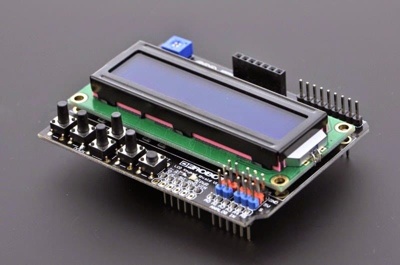
Table of Contents
  • Arduino LCD KeyPad Shield (SKU: DFR0009)
  • Library Explanation
    • Function Explanation
    • Example

Arduino LCD KeyPad Shield (SKU: DFR0009)

The LCD Keypad Shield is specifically created for working uniquely with Arduino boards, with a mission to allow a hassle-free and user-friendly interfacing operations for the users.

With this module users can now get well versed with the menu, and choose the variants as per their specific application conditions and desirability.

The Arduino LCD KeyPad Shield (SKU: DFR0009) module is designed with 1602 white digital characters, over a bright blue backlight Liquid crystal display panel.

It features a keypad with 5 keys, configured to deliver exclusive functions such as select, up, right, down, and left.

The module includes a digital IO (input/output) saving ability through a single analogue to digital converter or ADC channel.

The key pressing command is identified internally via a 5-stage potential divider network.

The explained Arduino LCD KeyPad Shield (SKU: DFR0009)  LCD module has become pretty popular due to its easy compatibility with Arduino boards.

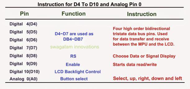
The display is made up of 2 by 16 LCD slots, assisted with 6 push to ON switches. Pin#4,5,6,7,8,9 and 10 work together for interfacing with an Arduino board.

The analogue pin#0 is assigned to scan the push button commands.

The module features an attached contrast adjustment control, and a back light ON/OFF option button.

The system also offers an expandable analogue pinouts for an hassle-free analogue sensor readability and presentation.

More details are enclosed HERE
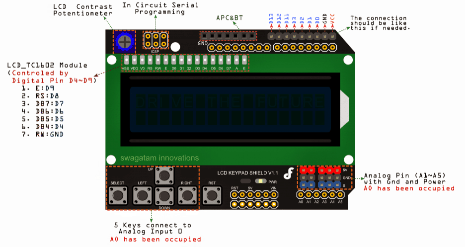
Image courtesy: https://www.dfrobot.com/wiki/index.php?title=File:DSC0410.jpg
The Main Features Included in a Arduino LCD KeyPad Shield (SKU: DFR0009) are:

  • Operating Voltage: 5V
  • 5 Push-to-ON buttons for toggling a custom menu panel for the intended selections.
  • RST button offers resetting of the concerned arduino program
  • Integrate a potentiometer for adjusting the back light
  • Available I/O pins are expandable
  • Analog Pinout expandable using standard DFRobot configuration for an enhanced sensor extension
  • Ideally suited Dimension: 80 x 58 mm

Library Explanation

Function Explanation

LiquidCrystal(rs, enable, d4, d5, d6, d7)

Generates a variable alternative of Liquid Crystal. The display screen can be commanded by means of the 4 or 8 data lines. If the first, pin numbers for d0 to d3 may be eliminated and maintain the relevant lines unused.

The RW pinout may be recommended to be connected with the ground rather than connecting to a pin over the Arduino board; in such a case, you may want to eliminate it from this function's parameters.

You may consider the following example for the same:

LiquidCrystal lcd(8, 9, 4, 5, 6, 7);

lcd.begin(cols, rows)

Triggers the interfacing of the LCD screen display, and assigns the
dimensions (width and height) to the display reading. begin() demands to be called prior to any different LCD library prompt, as an example:

lcd.begin(16, 2);

lcd.setCursor(col,row)

Fixes the location wherein the following inputs written to the LCD may become visible, for instance:

lcd.setCursor(0,0);

lcd.print(data)

Prints text for the LCD display, for example:

lcd.print("hello, world!");

lcd.write(data)

Writes a character for the LCD screen.

Example

The following example examines the LCD panel and the featured buttons. As soon as the user presses
the button over the shield,the screen instantly illuminates the relevant prompts.

Connection details: Simply Plug-in the LCD Keypad to the Arduino  board such as an UNO (or any similar controllers)

You'll also like:

  • Wireless Thermometer Using 433 MHz RF Link Using Arduino
  • fuel installationUltrasonic Fuel Level Indicator Circuit
  • 4069 IC Hex inverter pinoutIC 4069 Datasheet, Pinout Working, Applications
  • Smart Bathroom Exhaust Fan Controller Circuit with Sensors

Filed Under: Arduino Projects, Datasheets and Components Tagged With: Arduino, DFR0009, KeyPad, LCD, Shield, SKU

About Swagatam

I am an electronics engineer and doing practical hands-on work from more than 15 years now. Building real circuits, testing them and also making PCB layouts by myself. I really love doing all these things like inventing something new, designing electronics and also helping other people like hobby guys who want to make their own cool circuits at home.

And that is the main reason why I started this website homemade-circuits.com, to share different types of circuit ideas..

If you are having any kind of doubt or question related to circuits then just write down your question in the comment box below, I am like always checking, so I guarantee I will reply you for sure!


Previous Post: « Arduino RGB Flowing Sequential Light Circuit
Next Post: Making an Automatic Stopwatch for Runners, Athletes and Sportpersons »

Reader Interactions

Need Help? Please Leave a Comment! We value your input—Kindly keep it relevant to the above topic! Cancel reply

Your email address will not be published. Required fields are marked *

Primary Sidebar


Categories

  • Arduino Projects (95)
  • Audio and Amplifier Projects (134)
  • Automation Projects (18)
  • Automobile Electronics (104)
  • Battery Charger Circuits (90)
  • Datasheets and Components (109)
  • Electronics Theory (151)
  • Energy from Magnets and Earth (42)
  • Games and Sports Projects (11)
  • Grid and 3-Phase (20)
  • Health related Projects (27)
  • Home Electrical Circuits (13)
  • Indicator Circuits (16)
  • Inverter Circuits (98)
  • Lamps and Lights (161)
  • Meters and Testers (72)
  • Mini Projects (28)
  • Motor Controller (68)
  • Oscillator Circuits (30)
  • Pets and Pests (15)
  • Power Supply Circuits (91)
  • Remote Control Circuits (50)
  • Security and Alarm (65)
  • Sensors and Detectors (107)
  • SMPS and Converters (46)
  • Solar Controller Circuits (62)
  • Temperature Controllers (44)
  • Timer and Delay Relay (50)
  • Voltage Control and Protection (44)
  • Water Controller (37)
  • Wireless Circuits (31)


Circuit Simulator

circuit simulator image


Subscribe to get New Circuits in your Email


Other Links

  • Privacy Policy
  • Cookie Policy
  • Disclaimer
  • Copyright
  • Videos
  • Sitemap

People also Search

555 Circuits | 741 Circuits | LM324 Circuits | LM338 Circuits | 4017 Circuits | Ultrasonic Projects | SMPS Projects | Christmas Projects | MOSFETs | Radio Circuits | Laser Circuits | PIR Projects |


Recent Comments

  • Swagatam on Adjustable Voltage Regulator Circuit using LM324 IC with Over Current Protection
  • Swagatam on Adjustable Voltage Regulator Circuit using LM324 IC with Over Current Protection
  • David on Adjustable Voltage Regulator Circuit using LM324 IC with Over Current Protection
  • David on Adjustable Voltage Regulator Circuit using LM324 IC with Over Current Protection
  • Swagatam on How IC LM337 Works: Datasheet, Application Circuits

Social Profiles

  • Twitter
  • YouTube
  • Instagram
  • Pinterest
  • My Facebook-Page
  • Stack Exchange
  • Linkedin

Calculators

  • ZVS Induction Heater + Tank Calculator Tool
  • Zener Diode Calculator
  • Wire Current and Thickness Calculator (Ampacity Calculator)
  • Voltage Divider Calculator
  • Transistor Base Resistor Calculator
  • Transistor Astable Multivibrator Calculator
  • TL431 Calculator
  • Solar Panel, Inverter, Battery Calculator
  • Ferrite Core Air Gap Calculator Tool
  • Parallel MOSFET Calculator Tool: How to Connect MOSFETs in Parallel Safely
  • LC Resonance Calculator for EV Battery Charger Circuits
  • LED String Series Resistor Calculator
  • Calculator to Design a High Power 3kW PFC (Power Factor Correction) Circuit
  • Passive Power Factor Correction (PFC) Calculator
  • LM567 IC Calculator Tool
  • SMPS Flyback Boost Converter Calculator
  • Shunt Resistor Calculator for Ammeters
  • SCR and Triac Gate Resistor Calculator
  • Battery Back up Time Calculator
  • Boost Converter Calculator (Non-Isolated)
  • Bootstrap Capacitor Calculator
  • Buck Converter Calculator
  • Buck-Boost Converter Calculator
  • Capacitance Reactance Calculator
  • DCM Flyback Transformer & Wire Gauge Wire Size Calculator Tool
  • Filter Capacitor Calculator
  • IC 4047 Calculator (Frequency and PWM)
  • IC 4060 Calculator
  • IC 555 Astable Calculator
  • IC 555 Monostable Calculator
  • IC SG3525, SG3524 Calculator
  • Inductance Calculator
  • Induction Heater Inductor and Resonant Frequency Calculator
  • Induction Heater Work Coil Calculator
  • Inverter LC Filter Calculator
  • LC Resonance Calculator
  • LED Current Calculator
  • LM317, LM338, LM396 Calculator
  • NAND/NOT Gate RC Values Calculator
  • NOT, NAND Gate Frequency Calculator
  • Notch Filter Calculator Tool
  • Ohm’s Law Calculator
  • Phase Angle Phase Shift Calculator
  • Power Factor (PF) Calculator
  • RC Filter Calculator
  • Reactance Calculator
  • Sine Table Calculator for SPWM Arduino Code
  • Small Signal Transistor(BJT) and Diode Quick Datasheet
  • SMPS Calculator for Toroidal Ferrite Transformers
  • SMPS Flyback Transformer Calculator – Design by Target Duty Cycle
  • TL431 Calculator
  • Op-Amp Hysteresis Resistor Calculator

© 2026 · Swagatam Innovations