In this article I have explained a relatively simple triac controlled automatic mains voltage stabilizer circuit, which uses logic ICs and a few triacs for controlling the mains voltage levels.
Why Solid State
Being solid state in design, the voltage switching transitions are very smooth with minimum wear and tear, resulting in efficient voltage stabilization.
Discover the whole construction procedure of this unique, solid state mains voltage stabilizer.
The proposed circuit of a triac controlled AC voltage stabilizer will provide an excellent 4 step voltage stabilization to any appliance at its output.
With no moving parts involved its efficiency is further enhanced. Find out more of this silent operator: power guard.
The circuit of an automatic voltage stabilizer discussed in one of my previous articles, though useful, due to its simpler design, does not have the capability of controlling the different levels of varying mains voltages discretely.
The proposed idea though not tested, looks pretty convincing, and if the critical components are properly dimensioned, should work as expected.
The present circuit of triac controlled AC voltage stabilizer is outstanding in its performance and is almost an ideal voltage stabilizer in every respect.
As usual the circuit has been exclusively designed by me. It is able to control and dimension the input AC mains voltage accurately through 4 independent steps.
The use of triacs make it sure that the changeovers are quick (within 2 mS) and with no sparks or transients usually associated with relay type of stabilizers.
Also since no moving parts are employed, the entire unit becomes completely solid state and almost permanent.
Let’s proceed to see how the circuit functions.
CAUTION:
EACH AND EVERY POINT OF THE CIRCUIT PRESENTED HERE MAY BE AT AC MAINS POTENTIAL, THEREFORE EXTREMELY DANGEROUS TO TOUCH IN SWITCHED ON POSITION. UTMOST CARE AND CAUTION IS ADVISED, USE OF A WOODEN PLANCK UNDER YOUR FEET IS STRICTLY RECOMMENDED WHILE WORKING WITH THIS DESIGN .... NEWBIES PLEASE KEEP AWAY.
Circuit Operation
The functioning of the circuit may be understood through the following points:
Transistors T1 to T4 are all arranged to sense the gradual rise in the input voltage and conduct one after the other in sequence as the voltage rises and vice versa.
Gates N1 to N4 from IC 4093 are configured as buffers. The outputs from the transistors are fed to the inputs of these gates.
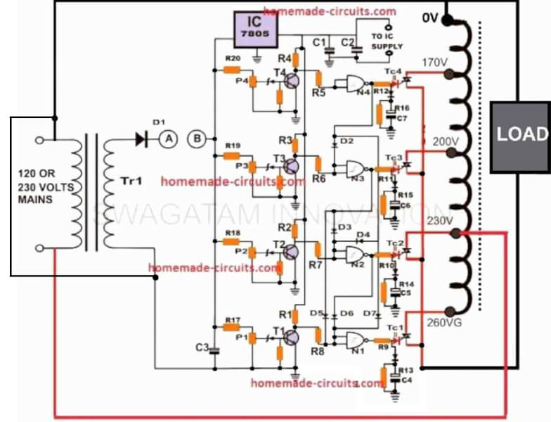
All the gates are interconnected to each other in such away that the output of only a particular gate remains active at a given period of time according to the level of the input voltage.
Thus, as the input voltage rises the gates respond to the transistors and their outputs subsequently become logic hi one after the other making sure that the previous gate’s output is shut OFF and vice versa.
The logic hi from the particular buffer is applied to the gate of the respective SCR which conducts and connects the relevant “hot” line from the transformer to the external connected appliance.
As the voltage rises, the relevant triacs subsequently select the appropriate “hot” ends of the transformer to increase or decrease the voltage and maintain a relatively stabilized output.
How to Assemble the Circuit
The construction of this triac control AC power guard circuit is simple and just a matter of procuring the required parts and assembling them correctly over a general PCB.
It is pretty obvious that the person who is attempting to make this circuit knows a bit more than just the basics of electronics.
Things may go drastically wrong if there is any error in the final assembly.
You will require an external variable (0 to 12 volts) universal DC power supply for setting up the unit in the following way:
Assuming that an output supply of 12 volts from TR1 corresponds to 225 volts input supply, through calculations we find that it will produce 9 volts at an input of 170 volts, 13 volts will correspond to 245 volts and 14 volts will be equivalent to an input of approximately 260 volts.
How to Set Up and Test the Circuit
Initially keep the points “AB” disconnected and make sure the circuit is totally disconnected from the AC mains.
Adjust the external universal power supply to 12 volts and connect its positive to the point “B” and negative to the common ground of the circuit.
Now adjust P2 until LD2 is just switched ON. Reduce the voltage to 9 and adjust P1 to switch ON LD1.
Similarly, adjust P3 and P4 to illuminate the relevant LEDs at voltages 13 and 14 respectively.
The setting procedure is now complete. Remove the external supply and join points “AB” together.
The whole unit may now be connected to the mains AC so that it can start working right away.
You may verify the performance of the system by supplying a varying input AC through an auto transformer and checking the output using a digital multimeter.
This triac controlled AC voltage stabilizer will shut OFF at voltages below 170 and above 300 volts.
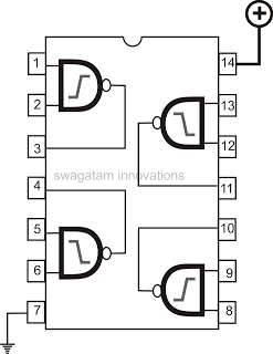
IC 4093 Internal Gate Pinout Arrangement
Parts List
You will require the following parts for the construction of this SCR control ac voltage stabilizer:
All resistors are ¼ Watt, CFR 5%, unless otherwise stated.
- R5, R6, R7, R8 = 1M ¼ watt,
- All Triacs are 400 volts, 1KV rated,
- T1, T2, T3, T4 = BC 547,
- All zener diodes are = 3 volts 400 mW,
- All Diodes are = 1N4007,
- All presets = 10K linear,
- R1, 2, 3, 4, 9, 10, 11, 12, 13, 14, 15, 16, 17, 18, 19, 20 = 1K ¼ watt,
- N1 to N4 = IC 4093,
- C1 and C3 = 100Uf/ 25 volts,
- C2 = 104, ceramic,
- Power Guard Stabilizer Transformer = “Made to order” having 170, 225, 240, 260 volts output Taps at 225 volts input supply, or 85, 115, 120, 130 volts taps at 110 AC input supply.
- TR1 = Step down transformer, 0 – 12 volts, 100 mA.



Questions & Answers
Hi Anil, you will need an appropriately designed autotransformer with outputs ranging from 90 to 450V for tacking this issue, then use this transformer with the following circuit the automatic changeover actions.
https://www.homemade-circuits.com/2011/12/how-to-make-accurate-7-stage-op-amp.html
Thanks!
You will require a variable DC power supply for setting up the relay activation thresholds, there's no other way.
Here's one circuit that you can try:
https://www.homemade-circuits.com/2011/12/how-to-make-accurate-7-stage-op-amp.html
voltage level meter can be built by modifying the following circuit:
https://www.homemade-circuits.com/2013/08/make-this-10-step-battery-voltage.html
sir, can u tell me where should i connect the terminal of tapping transformer with the triac terminals. i have done all the things and the sensor circuit is working accurately but i couldn't get the output., and the entire tapping transformer connection
Sandeep, the load should be between the MT1 of all triacs and ground, that is between the left leads and the common ground, however it seems this could pose some problems, I'll try to correct it soon if possible within two days.
thanks for your concern sir, please correct it as soon as possible for you.
you can do one thing, connect the load in series with the common mains input of the transformer.
suppose your transformer has 5 wires, one out of these will be the common "cold" input wire and other will be the "hot" ends…connect these hot ends with the triacs as shown in the diagram and connect the load in series with the common or the "cold" wire
if we do like this then we get 2-3V across triac but we have connected one of the wire of the transformer(say 135v) to the triac.we can not step up this voltage to 220V. if we take same common it will effect the circuit because one side is electronic circuit and other side electrical circuit, if we take same common the entire circuit changes abruptly and its behaviour changes.
I have updated the diagram, please check it out.
do not use D8…remove it
okay sir and thanks for the help.. thanku..
sir, my transformer has 4 hot wire(tapping) 1 common terminal and 1 output wire. and i have done all the thins as u mentioned in the diagram but still the circuit is not working and we are not getting the output as desired. sensor part is working properly, if we connect the transformer according to the diagram we are not gettng the output. please help us.
Do the LEDs light up in sequence while testing with an variable input?
if yes, then you can confirm whether the triac corresponding to the illuminated LED is conducting or not….short the MT1, MT2 of the triac with a wire manually this should actuate the load, if it doesn't then probably there could be some problem with the triac…. check it as per its datasheet…if not then the trafo configuration could be assumed to be incorrect and not as per the shown diagram…
LEDs are working sequentially and triacs too. sir, we have 3 terminals of the triac. MT1 is shorted with ground. gates are trigeering. MT2 are connected with 4hot wires(tapping) of transformer. and load is connected according to the diagram. what is the meaning of this 0V? we have connect load across i/p voltage and output of the transformer(say 220v, taken 0V as 220v). still problem is same,
0V refers to the first tap which may be near most to the "hot tap" assigned with the minimum volts, in the diagram its the 170V tap
if your triacs are connected in the manner you have specified then they must conduct, and if any one of the triac conducts, the input entering through the load has to pass through the triac and reach the other end of the mains through MT1 to MT2…and since the load is connected in series with this mains line it has no other option but to switch ON.
as I mentioned before, try shorting the MT1/MT2 of the triac which has its gate LED illuminating, this should toggle the load ON/OFF, confirm this manual operation. if this happens would indicate towards a non-conducting triac….this could be due to a insufficient gate voltage/current, reduce the gate resistor value and recheck…
sir we have already done it. theoratically it is correct but practically it is not giving the output. sir, have u done it practically? this project belongs to our final yr project and we have to submit it within 1 week and we dont know what to do. we went through all the possibilies but result is still zero. practically u have done it na sir.
Sandeep, the theoretical part that you are confused with is a simple electrical wiring, since you have reached and successfully built the complex section of the circuit, troubleshooting this simple electrical issue should not be a problem at all according to me, the triacs are just acting like switches, so replace the triac MT1/MT2 with a manual short as I mentioned earlier to identify and trace the electrical path.
I have not checked it practically but as you have tested it yourself the circuit sections actually work as explained, it's only a simple electrical path that you are not able troubleshoot, imagine a design without the circuit rather only with the trafo, the load and switches, simulate it practically and then replace it with triacs to check the results, you can seek an experts help if you finally fail to troubleshoot the fault
I have reassessed the transformer wiring/triac/load and I think I have understood the problem, I'll correct it and try to update it soon…
I have updated the corrected diagram, you can check it now.
this circuit should work because previously the load was in series with the main input. we can not get the constant output voltage across load.
OK… please check it and let me know
actually sir we have a holiday of 3 days. so college is closed and we dont have the required equipments. i will do it on monday and i will tell u the result.
OK, no problem!
Hello Friend !
Nice Job !
But I have a question !
Can i use your project to do this :
In – 85 ~ 240 vac
Out – always 225vac
Hello Jose,
yes it is possible but that might require the inclusion of more number of triac stages, may be up to 10 or 12, and corresponding numbers of tapping from the stabilizer transformer.
Ow sure !
Thank you that was prompt ! And how about the Resistors in base & emitter of all the transistors(T1-T4) ? I know they are not crucial, so can I pick 10k 1/4w value ?
the transistor resistors can be left as is, they won't require any change, in fact the entire design will be exactly the same, only the stages will need to be repeated more number of times as per the specifications. This will require more number of ICs to be included along with the corresponding transistor and the triac stages.
Yes I understand that it is not necessary to change the circuit. But you do not quote the values of resistors between base and emitter .
yes 10K will do, and 1uF for the capacitor, the diode can be a 1N1448 or a 1N4007
…sorry I thought you were asking about the triac gate configuration, …anyway 10k for the transistor bases is perfect, no issues.
HELLO, SWAGATAM, THANKS FOR THIS CIRCUIT, I WILL MAKE THE PCB AND POST IT HERE AND I CAN DESIGN THE AUTOTRANSFORMER FOR THIS PROJECT, SO I NEED THE MORE LOAD I MEN 5 KV THEN WHICH TRIACS I HAVE TO USE.
THANKS
Hello, Sawagatam, thanks for your circuit, I guess you do not have good idea about the transformer winding and design, I can make the transformer for you here, i need tow thins here I want to add one more tap and 5kv load so what have to change the triacs? I will draw the pcb and i will send here for all users.
thanks
Thank you Imran, I appreciate your help. The only difficult part with an autotransformer is the number of turns, core dimension and the wire gauge, but making it can be actually easy, it's just about winding one long single continuous winding with taps removed at appropriate points across the length of the winding.
For 5kv you can upgrade the tracs with BTA41/600 it will be strong enough to handle 5kva easily
I'll make sure it gets posted in the above article, as soon as you send me the mentioned details
best regards.
Hello Swagatam Majumdar and Imran Khan
I like it I can also help this blog design the PCB and we can upgrade to micro controller level.
But I can not make transformer. if you design the pcb and how to winding the transformer please help me am live in Africa, Ethiopia my power fluctuation from 120 – 200VAC but I need constant output range 220 – 240. Help me, Life was complected due to power problem if you can please email me kaledawitesmelealembd@gmail.com
Hello Imran,
I am not very sure about the winding data, however you can do one thing, you can take a readymade 5amp transformer and unwind the primary section and count how many winding it had in it. Then you can rewind it by adding 100 turns more to it.
You can take out taps at regular intervals from the last 150 turns to get a range of 170, 190, 210, 225, 240, 260, 280, 300V
Hello Dear Sandeep sharma
plz help me you already proof in practical as ur comment.
plz email me the necessary documents and steps
it's an auto-transformer design…you can Goggle the same for more info
dear swagatam, would you like to help me with my project here
i'm working on with my project using solid state triac to control the current of a circuit and make it constant, and i'm using arduino UNO board for my project
Dear swagatam,
How can I stabilize the frequency to 50 Hz with this circuit ? Which component can be able to do it ?
this circuit will stabilize the voltage conditions only, frequency cannot be stabilized with this circuit
Sir,
Mai apse baat karna chahta Hun.pls.mere mob.num.07258035390,anitchittu@gmail.com par den.
wel done Sir… I like this circuit.
Sir can I use one transfor that has its one 12v 2A instead of using Tr1?
thanks aminu, yes definitely you can use a single trafo with a separate 0-12 winding for operating the circuit
Dear Swagatam,
I had followed the stab as per your given design except triac control is done by optoisolated 3041 mooce IC and arduino.The individual switching is done very good. but when I connect all traic put together the output is no more as sequence.
Dear D’Patil,
Since you are doing it through an Arduino I will not be able to interpret functioning and troubleshoot the design, I might be able to help only if the circuit is built exactly as given in the article.
thanks for prompt reply, Arduino side has no issue i had put led to indicate the trigger, it is according to adc increase due to ip voltage.The problem is when all traic are connected the output follow exactly like input.i.e. input increases, op increase and vice versa. individual switching of traic is there, but how this collectively happen can’nt trace.can you just a though over it for my help. when I connect indiv. traic and Xmer connection it works exactly.but in all traic connected it won’t while traic switching is also correct.Pls…
Only one triac should be ON at a given instant, is this happening correctly in your design? If only triac is conducting at a given instant, then that particular tap must power the load with the specified voltage…so I am not able to figure out how the procedure is giving trouble?
Hi,Am Edward, Thank you for the circuit. I have the following questions:
1. I want to do 50kva 3ph.what do I need to do on the circuit to handle this.
2. My voltage surges to 600v ph-ph.what windings and transformer do I need?
Advice,
Edward
Hi Edward, for a 50kva load yo may have to go with appropriately SSRs, you can try the the following concept:
https://www.homemade-circuits.com/2011/12/diagram-shows-rather-simple-voltage.html
I feel use of triacs in place of relays may be un-reliable as accidental output short circuit will damage the triacs and if by any chance they get shorted as a result, the transformer will burn. Shall appreciate if any hardware tested circuit is published in place of an untested design.
you can try the following concept with relays, this was successfully tried by one the readers:
https://www.homemade-circuits.com/5-kva-to-10-kva-automatic-voltage-stabilizer-circuit/
sir,please tell me ,in this diagram where the terminals go to from written as ” TO IC SUPPLY”. please tell me hurry up sir.