In this article I have explained a set up for testing MOVs which are special devices specified for absorbing instantaneous high surge currents that may accidentally occur in our mains electrical lines. The idea was requested by Mr. Kevin
Technical Specifications
I'm Kevin Montañez, a university Electrical Engineering student here in Cebu, Philippines. As I told you before, I will get back to you if I have more questions. 🙂
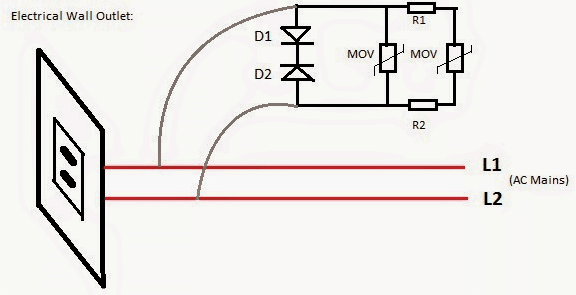
I am hoping you'll entertain my query again. Attached is the surge protection circuit we have decided for our group research/thesis. This is just one part of our project which is to have a built-in sure protection for wall outlets using 2 diodes with cathodes connected to each other and MOVs.
Although you have recommended before to use NTC thermistor instead of fuse or diodes, but I am concerned that it will cost much than the diodes. These are my questions:
1. Here in the Philippines, it is not practiced to have grounding in most residential buildings unless residential buildings for rich people of course they have.
Many buildings here are connected line-to-line instead of line-to-ground as practiced abroad. One of the characteristics of MOV is to absorbed excess voltage, where its resistance will drop, eventually current will flow to it and will be absorb.
The absorbed current will be dissipated to the grounding rod. My question is, how to dissipate the current in a line-to-line connection?
I am asking this so that by the time we will defend for our thesis, we could test it in front of the panel, sadly the school is not line-to-ground connected, and outlets don't have grounding connection.
2. How to test the varistor (MOV) to know if it really works? If it really absorb the surge voltage/current? Say for example, if a motor will be connected in our proposed outlet, it will require a large starting current. How to check if the varistor really absorbed it? What instruments do we need to conduct such testing?
3. How to test as well the 2 diodes with cathodes connected to each other?
4. I'm curious as well since you recommended before to use NTC thermistor, what usual rating would it be for the thermistor for this kind of application? How to test if it work?
I'm praying that you will read and respond to this soonest. I'll attach my email address if you prefer to respond there.
You really are a big help for our thesis and your blog and ideas are a great help as well especially for us students. Please do help us pass this subject.
Thank you very much for sharing your knowledge in Electrical Engineering! Gob bless you more!!!
Best regards,Kevin Montañez
Solving the Circuit Query
An MOV is required to be connected across LINE and NEUTRAL and not LINE and GROUND, so ground may not be required for MOVs, basically it simply needs to be connected across the load mains input terminals.
An MOV is designed to protect against instantaneous high voltage surges that may last for not more than a few nano seconds....for example if there's an instantaneous voltage spike of say 600 V for 3 nano seconds, the MOV will happily neutralize it by short circuiting it across the connected terminals.
However if this spike sustains even for a second it could cause the MOV to get destroyed and catch fire.
To demonstrate how to test an MOV you would need a 600 V AC source derived by stepping up the domestic 220 V through an auto transformer, and make the circuit set up as shown in the diagram.
Circuit Setup
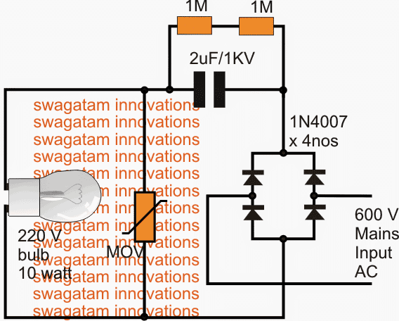
The figure shows a bridge network which rectifies the 600 V AC to 700 V DC and this DC is then fired across the MOV circuit carrying a vulnerable 220 V, 10 watt lamp.
This is done through a 2uF/1KV capacitor in order to protect the MOV as it's not designed to handle sustained high surges.
Normally the connected lamp would instantly get burnt when subjected to this massive 700 V, but the experiment will hopefully show how the massive voltage is successfully absorbed and neutralized by the MOV saving the bulb's life.
The diode set up is not recommended, because TVS diodes can act like short circuit if they happen to get destroyed, this would mean the wires catching fire or the fuses blowing of.
An NTC can be selected as per its maximum voltage rating specs, this voltage rating will determine how much instantaneous high voltage the device is rated to restrict.
A Very Simple MOV Tester Circuit
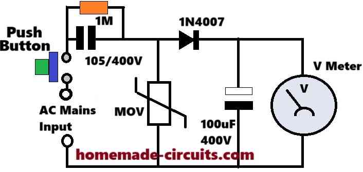
The above design appears to be a simple and an effective MOV tester circuit which can be quickly used to verify the clamping voltage of any MOV. It can be also used to verify whether the MOV is actually good or a bad one.
The idea is simple, when we press the push button, the mains AC is passed through the 105 (1uF) capacitor and applied across the MOV.
If the MOV is working good, it will instantly ground the excess voltage and not allow the input voltage to rise above the specified clamping voltage of the device.
Thus, the maximum voltage will not be allowed to go past the clamping voltage of the MOV, and this cut-off voltage information will be delivered through the 1N4007 and stored inside the 100uF capacitor.
Since a voltmeter is connected across this 100uF capacitor, the meter will quickly provide you the voltage reading at which the MOV restricted the input mains voltage level.
If the voltmeter reading matches the clamping specification of the MOV that would indicate the MOV is good, any other results might indicate towards a faulty MOV.


Questions & Answers
Hi Mr. Swagatam, I cannot see the my former post here but see your answer at my e-mail box. So need to rewrite the subject and also remind the one point. My appliance runs with 110V AC and it has the burnt varistor.(I can not see the value but it should be proper for the 110V AC). Now I will use a serial 150uF capacitor to test it with the 220V AC as you had suggested. So please advise should I replace any varistor instead of the the burnt one or no necessary?
Hi Suat, Due to a technical problem in my site, I had to restore the previous days backup, and that is why many of the current days comments were removed.
If you use a varistor with 220V then it must be rated at 340V. But for your application, MOV is not important, instead an NTC may be more useful.
So if possible please try a 5 ohm 10 amp NTC in series with the 150uF capacitor.
thermistor is good for temperature control voltage ⚡ does help with mov alternative ??.
Yours email ID ?? I would be able to send you a lot more information. Hope you can help.
Thanks
Hubert
Hi, I saw the images you sent to my email.
When I tried to investigate online about S750 I could not find any information about it, however from the diagram that you have drawn, the S750 seems to be in series with the mains supply after the MOV, which clearly indicates that the S750 part should be an NTC thermistor.
But when I tried to search more about NTC S750 I could not find any relevant information.
You said that the resistance of the S750 was 10 ohms, that means it is simply a 10 ohm NTC thermistor.
The place indicated as RT201 on the board where the S750 was mounted looks like a capacitor, but everything else indicates towards an NTC, I thing the manufacturer has intentionally used confusing labels just to make sure nobody is able to copy the design easily, it’s just a guess by me though. Let me know if you any further doubts or questions.
My email ID is
homemadecircuits
@gmail.com
My dehumidifier has the MOV and one more ????? S750 or S75o unable to find a schematic or what this item is help would be greatly appreciated. Whirlpool dehumidifier model AD70GUSB.
Hope you can help. This is used before the load. What would be the symbol use on board # RT201 where this s750 item is used.
Hi, I tried to find the details of S750 online, but could not find any information about it.
please provide the image of the MOV location, component side view and PCB side view and send it to my email ID, I will try figure it out…
My dehumidifier has the MOV and one more ????? S750 or S75o unable to find a schematic or what this item is help would be greatly appreciated. Whirlpool dehumidifier model
AD70GUSB.
Hi, sorry, I could not identify either what the S750 is? If you can tell me how this part looks like and how it is associated with the MOV, I can investigate more on this…
Hi Mr. Swagatam;
I have 120V AC 1000W air fryer home appliance and 14N511K varistor
is being used on the circuit. Could it be possible to use the 275V varistor instead
since the input mains is 120V.
Regards
Hi Suat, yes that’s possible, however since the maximum peak of a 120V AC is around 160V, I think the clamping voltage of the MOV should be around 180V.
Hi,
How to design a surge protection circuit for the boilers, to protect triac which controls heating element and PCB without burning them. In this case I don’t know about the max spike voltage value as it differs with respect to location. Please give me any direction or guidance. Thank you very much.
Hi,
You can try applying a snubber network across the triac for protecting it against voltage and current surges. Here’s an article which explains the procedure in details, or you can also search online for similar designs:
https://www.homemade-circuits.com/understanding-triac-snubber-network-calculations/
Good day
please why does the MOV keep blowing up when connected to the mains even without load?
thank you
MOVs are designed to shunt high voltages/currents only for a period of a few milliseconds. If the surge current sustains beyond a few millisecond time then the MOV will burn. If your mains AC supply has frequent high voltage high current fluctuations with periods longer than a few milliseconds then the MOV will burn. Check it the response with a load connected, because load sometimes can absorb high fluctuations and in fact prevent the MOV from burning.
I am just starting to learn electronics, I’m not a student, just an old guy trying to keep the gray matter functioning. I have a small refrigerator unit that quit , nothing works, I found that a 47 ohm resister burn out and replaced it. Plugged it in and it fried the resister again, I found that it is connected to a MVR10D431K varistor and thought I’d try changing that one. This unit has looks like 8 of these, do I have to change all of them ? It looks like they are all in series. The short is in the board because I started eliminating the harnesses from the fan, compressor etc.
I’m learning as I go, and at 76 it’s not as easy as it used to be!
Thanks
Al
I appreciate your interest to learn electronics at 76. Age is just a number. The varistor that you have mentioned is a 430V varistor. It is strange to have 8nos 430V varistors connected in series, that would mean a total clamping voltage of 430 x 8 = 3440 Volts which is extremely high for fridge protection?
Anyway, I think yes, you must try changing all of them and see if that helps, but I somehow feel that the short could be somewhere else. The only way to troubleshoot would be to replace each of the components one by one, since we do not have the full schematic drawing of the board, so pinpointing the fault looks difficult.
Thank you, that is my plan as I feel I’ll hopefully learn more rather than just replacing the board. I came up that high number also, but wasn’t sure if I used the same formula as adding resisters. I know I’m ahead of myself tackling this, however I’ve always was a hands on type, and seemed to remember things doing rather then just reading about it. I did learn there is a path to trace on the top as well as the bottom.
Again thank you,
Al
Sure, I hope it helps you to learn more about the subject. All the best to you!
Thanks again!
sir how can i confirm if a varistor is bad
best regards
AKANDE JOSEPH
Akande, there’s no easy way to test it, a bad MOV can be shorted internally or open….the above explained set up can be tried
Hi sir
I am akram,a university student from sri lanka.. first i would like to thank you for the excellent work of publishing articles and helping out students.
Sir. i need to develop a surge arrestor monitoring device which measure surge currents and when it about to reach its maximum capacity, the device should give signal to remote pc.basically a surge counter
pls help me with this project sir
many thanks
Thanks for posting Akram, If possible I'll try to figure it out and post it soon in this website.
Good day Sir Swagatam
Thanks for your Email on topics about “How to Select MOV” posted on : 09 May 2016 02:15 AM PDT.
Sir, I make a ‘Android Mobile Charge Controller’ using IC MC34063 (DC12v to DC5v).
Same here, I like to use a ‘POLY switch’ (XF075) for protection OVER LOAD through Output. !!
So, how could I use that ‘POLY switch’ on Output to Limit the Current flow?
Please, guide me with the circuitry for solving above.
Thanks & best regards,
S. Imran.
Image Link: &imgrefurl=http%3A%2F%2Fhotitem.bizcoco.com%2Fshow%2F1399310%2FPtc-Resettable-Fuse-Schematic-Symbol.html&docid=IHT2znW7BGqmaM&tbnid=GPiQV2xdAy7m3M%3A&w=800&h=640&bih=623&biw=1366&ved=0ahUKEwiE9LXx8ZLNAhUKQI8KHWUQBjUQMwg0KBMwEw&iact=mrc&uact=8
Hi Syed, Polyswitches are similar to NTCs but with a feature of resetting to its original state once the over-current condition is removed.
You just have to put it series with the positive or the negative supply line of your power supply for the intended protection…..but make sure to use the correctly rated device so that it trips at the right over current specification
how to test mov either good or bad and how to check that mov continuity using digital multimeter
Hello sir u have led series dc tester..to find the damaged led easily .and sir i want to find damaged led which operates on 230v ac main …….
hello basit, you can use a 3v button cell and connect it across the leds, if the led lights up brightly you may assume it to be working otherwise not.