The post describes simple battery charge monitor circuits or battery status indicator circuits using 4 LEDs to 10 LEDs, and using ICs like LM324 and LM3915. The first design is a 4 LED voltage monitor circuit using the versatile IC LM324. The idea was requested by Ms. Piyali.
Technical Specifications
I've a project, if you could help me out:
1. basically its a battery voltage detector cum indicator circuit.
2. the output from a transformer is 6V, 12V, 24V resp., depending on the supplied input. O/p is A.C.
3. by converting it into D.C. I've to design a circuit which will detect and indicate the voltage o/p by colored LED lamps. Such as,
Blue LED - 6V
Green LED - 12V
Red LED - 24V
4. Circuit should be compact in nature as much as possible.
.
Query:
1. should we be using comparator circuit ?
2. how to detect the diff. voltage levels ?
3. Is relay required ?
.
Please consider at earliest.
1) The Design
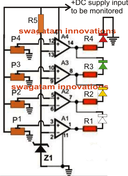
The proposed battery voltage status monitor circuit using 4 LEDs makes use of comparators in the form of opamps from the IC LM324.
This IC is much versatile than the other opamp counterparts due to its higher voltage tolerance level and due to the quad opamps in one package.
In the proposed LED battery voltage monitor/indicator circuit all the four opamps have been used, although a few of them may be eliminated in case they are not required or depending on the specs of the individual users.
As can be seen the circuit diagram, the configuration is simple yet the outcome too effective.
Here the inverting pins of all the four opamps are clamped to a fixed reference level determined by the value of the zener diode which is not critical and can be any value close to the suggested one in the parts list.
The non-inverting pins of the oipamps are configured as the sensing inputs and are terminated with variable resistors or the presets.
How to Adjust the Thresholds
The preset should be adjusted in the following manner:
Initially keep all the presets slider arm shifted toward the ground end so that the potential at the non inverting pins become zero.
Using a regulated variable power supply apply the first voltage to be monitored starting from the lowest value to the circuit.
Adjust P1 such that at the above level the white LED just lights up. Fix P1 with some glue.
Next apply the second higher voltage or increase the voltage to the next level which is to be monitored and adjust P2 such that the yellow LEDs just switches ON. This should instantly shut OFF the white LED.
Similarly proceed with P3 and P4. Seal of all the presets after they are set.
The shown battery indicator circuit is configured in the "dot" mode meaning only one LED glows at any instant indicating the relevant voltage level.
If you want to make it respond in a "bar graph" mode, simply disconnect the cathodes of all the LEDs from the existing points and connected them all with the ground or the negative line.
Circuit Diagram
Parts List for the battery status monitor circuit
- R1---R4 = 6K8
- R5 = 10K
- P1---P4 = 10k presets
- A1----A4 = LM 324
- z1 = 3.3V zener diode
- LEDs = 5mm, color as per individual preference.
The above circuit can be also configured in the following manner:
How it Works
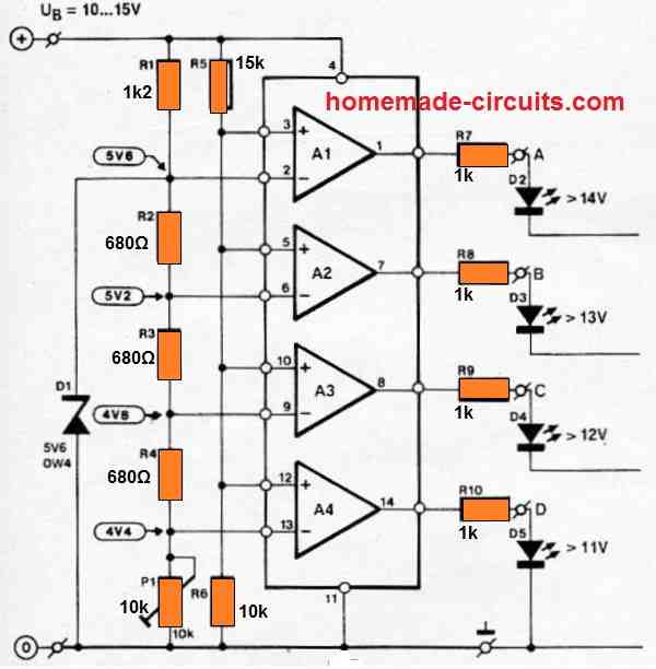
The LED voltmeter discussed is generally used to track the charging and discharging of a vehicle battery. Because of its tiny size, it may be placed almost anywhere on the dashboard. The device is based on a low-cost quad opamp Type LM324, which may be powered directly from the automobile battery.
A comparison of the battery voltage and a reference voltage from each of the four opamp inputs generates the voltage readout. The reference voltage is generated using a zener diode connected to a bias resistor R1 and allowing a current of roughly 6 mA. 5V6 was chosen as the zener voltage because zener diodes running between 5 and 6 V have the highest thermal stability.
ALL THE LED CATHODES ARE SUPPOSED TO BE CONNECTED TO THE GROUND LINE.
2) Modifying the above 4 status Battery Indicator with Flashing LEDs
The above explained 4 LED battery status indicator can be modified appropriately for enabling it with flashing LED indicators, as shown in the following diagram:
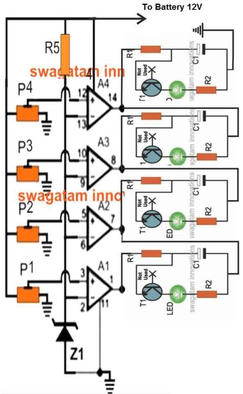
- R1 = 2k2
- R2 = 100 ohms
- LED = 20mA 5mm type
- C1 = 100uF to 470uF depending on flashing rate preference
The article shows a simple method of using the IC LM3915 for monitoring battery voltages right from 1.5V to 24V in 10 discrete steps using 10 LED indicators.
3) Using a LM3915 IC for the 10 Step Function
The third circuit I have explained below allows you to visualize precisely what voltage your battery has at any particular instance while it's being charged.
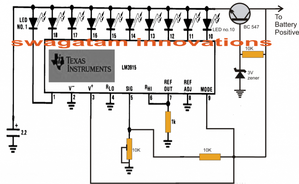
The LM3915 is basically a 10 stage dot/bar mode LED driver circuit which provides a sequential 10 step LED display corresponding to the varying voltage levels set at its signal input pinout#5.
This input can be set with any voltage level right from 1 to 35V for acquiring a correspondingly sequencing readout of the voltages fed on that pin.
In the proposed 10 step battery charging indicator and monitor circuit we assume the battery to be a 12V which is to be monitored, the circuit functioning may be understood as follows for the aforesaid condition:
The transistor at the right end is configured as an emitter follower replicating a high current, constant voltage zener diode, fixed at 3V.
This is required so that the LEDs are restricted from drawing excessive current, unnecessarily making the IC warm.
The battery voltage is also fed to pin#5 via a voltage divider network made from a 10K resistor and a 10K preset.
The outputs of the IC are all connected with 10 individual LEds for producing the required 10 step indications. The color of the LEDs can be as per your preference.
How to Set up the above explained battery status indicator Circuit.
- It's pretty simple.
- Apply the full-charge voltage level across the point indicated "to battery positive" and ground.
- Now adjust the preset such that the last LED just illuminates at that voltage level.
- Done! Your circuit is all set now.
- For calibrating, simply divide the above mentioned full charge level with 10.
- For the present case, let's assume the full charge level to be 15V, then 15/10 = 1.5V, meaning each LED would stand for an increment of 1.5V. For example with the 8th LED just ON would indicate 1.5 x 7 = 10.5V, 8th LED = 12V, 9th LED = 13.5V and so on.
- Similarly, the circuit can be used with any battery and just needs to be set as per the above guidelines for achieving the proposed 10 step battery level monitoring.
Circuit Diagram
Precision Car Battery Monitor Circuit
An accurate automobile battery monitor circuit is shown in the following image.
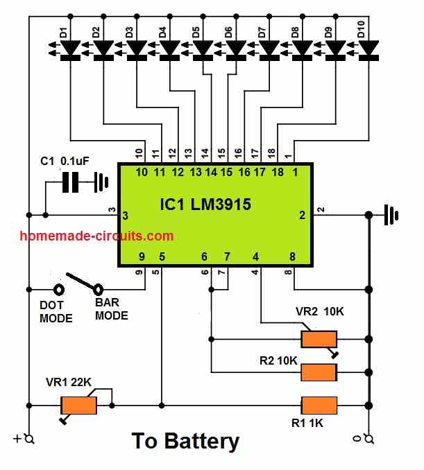
It only includes the IC LM3914 and 10 LEDs, along with some resistors. With VR2, you may choose the lowest limit of the measurement range at which the scale's first LED (D10) will illuminate.
Using VR1, a maximum battery voltage range is determined.
The scale's LEDs each indicate a tenth of the total measurement range. There won't be any LED illuminated if the voltage stays below the lower limit. D1 would stay illuminated if the voltage exceeds the upper limit.
How to Set Up
Practically any required measurement range may be specified using VR1 and VR2. As an illustration, let us consider an automobile battery whose level needs to be monitored.
Setting the top limit with VR1 to, say, 15 V is suitable given that the charging voltage is normally about 14.4 V. It is simple to do this by briefly connecting the circuit to a 15 V variable power supply source and rotating VR1 until D1 illuminates.
VR2 must be fully rotated clockwise throughout this adjustment process to avoid any adverse effects. The voltage that the lowest LED should display is what we need to figure out next.
For example, if we wanted each LED incrementing by 0.5V, the illumination sequence would be 15V, 14.5V, 14V, 13.5V, 13V, 12.5V, 12V, 11.5, 11V, and 10.5V.
The variable power supply source is now adjusted at 10.5V, and VR2 is tweaked until the lowest LED lights up.
Finished, that's all!
Don't forget that smaller increments of 0.33V or 0.25V as well as bigger increments of 1 V can be also made in the identical manner.
Begin by completely rotating VR2 clockwise, then tweak the upper voltage using VR1, then decrease voltage using VR2.
You'll see that the LEDs switch on and off gradually with very little increments, like 1/10 V, thus it may be feasible that two LEDs are illuminated simultaneously at a specific voltage level.
Dot Mode or Bar Mode
Both dot-mode and bar-mode may be used with the IC LM3914 or LM3915. Only one LED at a time will be illuminated in the first scenario. In the second situation, all of the relevant LEDs will be switched on depending the corresponding level of the voltage.
Pin 9 of the IC is used to switch between the two different modes. If it is left open, the IC will work in dot-mode. Bar mode is triggered once the switch is closed.
Car Battery Voltage Monitor Circuit
The first concept above can be also modified as a 4 LED car voltmeter which will allow us to monitor the voltage level of the battery of our car at any instant, continuously.
Main Features
To achieve the above feature it must be placed somewhere in the dash of the car so that the group of 4 LEDs remain protruded, each with a label indicating the battery voltage having at that instant.The circuit is designed for executing the following:
- 1st LED lights with 11V battery
- 1st and 2nd LEDs light with battery 12V
- 1st, 2nd and 3rd LEDs light with battery 13V
- 1st, 2nd, 3rd and 4th (all) LEDs light with battery 14V
Operational Details
When the battery voltage drops to 11 or 12 volts, it may need charging. If its around 13 volts it is in acceptable condition. At 14 volts it is fully charged. The colors of the LEDs indicate these status.
The main components of the circuit are just a few operational amplifiers used as comparators.
The inverting inputs of these operational are set at fixed reference voltages using resistor R1, and a zener diode D1 that may be rated at 3.3V or more, but below 6V.
The non-inverting inputs of the op amps are adjusted using the resistors R2, R3, R4, R5, R6. These may be calculated fixed resistors, or these may be replaced with 1 K presets so that the desired adjustment can be implemented for turning ON the LED at the respective battery voltages.
The battery voltage is delivered to non-inverting inputs of the opamps through the shown voltage divider networks formed by R4 and R6 terminals.
Depending on the battery voltage, the voltage at the non-inverting terminal will vary and will put a high voltage level at the output of the comparator, activating the corresponding LED for the required indications.
Circuit Diagram
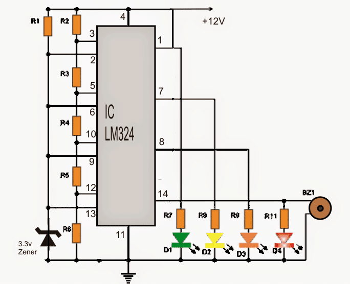
Parts list for the circuit
- IC1: LM324 integrated (quad opamps in a single integrated) Circuit
- D1: 3.3V zener diode, 1/4 watt
- D2 = D3 = D4 = D5: Diodes LED (2 red, 1 yellow or amber, 1 green)
- R1 = 1K
- R2.....R6: all 1K preset
+12V: is the car battery whose voltage is to be sensed
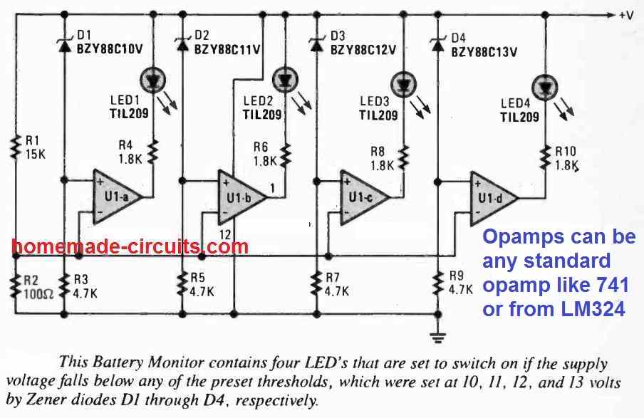
Another simple 4 LED battery monitor circuit is shown in the following image, using the IC LM324:
Miscellaneous Easy Battery Monitor Circuits
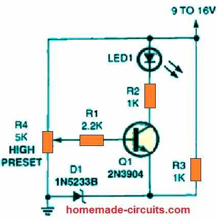
The first circuit is an battery over voltage indication circuit that replaces the IC-based design with a single transistor. The base of transistor Q1 is coupled to the preset potentiometer, R4, while the emitter of transistor Q1 is hooked up to a 6 volt Zener reference.
No collector current is able to flow and the indicator LED1 remains shut off as long as the voltage at the base of Q1 is less than 6.6 volts. Q1 switches on and lights the LED if the base voltage rises over this value. R4 can be adjusted to enable the circuit to detect and monitor the desired voltage level.
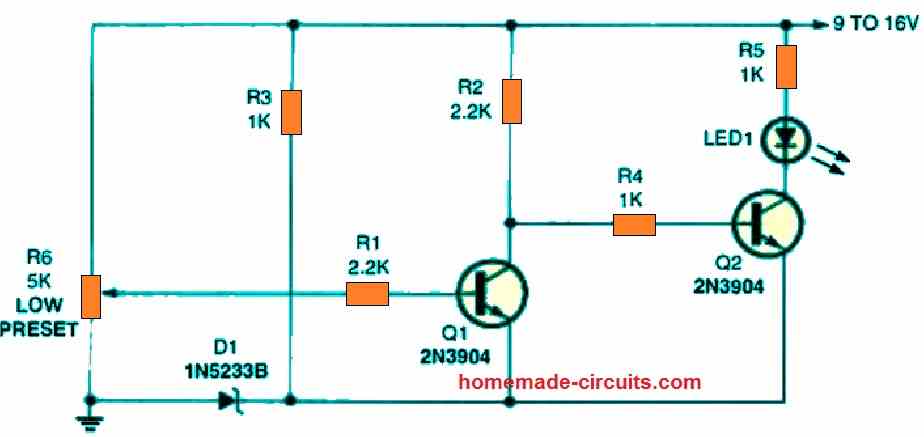
In the following circuit, we add a second transistor to our previous circuit, converting it from an over-voltage to an under-voltage battery warning circuit.
This is how it goes.
Firstly, potentiometer R6 is set to switch transistor Q1 off at the desired low-voltage limit. When Q1 is switched off, the collector voltage rises, providing a positive bias for the base of transistor Q2.
This bias activates Q2 and illuminates LED1. Transistor Q1 is turned back on when the supply voltage returns to normal, this situation now forces transistor Q2 and the LED to switch OFF.
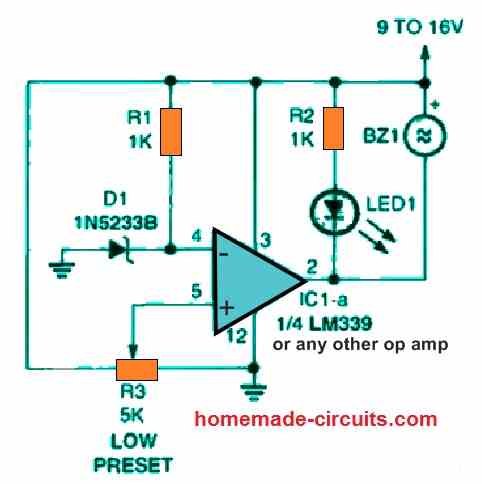
One portion of an LM339 quad voltage comparator IC is used at the center of the this battery monitoring circuit. The negative input voltage of the comparator is fixed by a 6 volt Zener diode reference, while the positive input of the IC is adjustable.
The output at pin 2 of the IC would be high as long as the voltage at the comparator's positive input is higher than the voltage at its negative input, leaving the LED switched OFF and the buzzer silent.
The comparator's output turns low the moment these input parameters are inverted, illuminating the LED and activating the piezo device.
Find the low voltage threshold and tweak potentiometer R3 to provide an output at this voltage level while building this circuit. R3 can be adjusted with just about any 4k7 potentiometer, however a multi-turn trimming potentiometer enables the tuning to be considerably simpler.
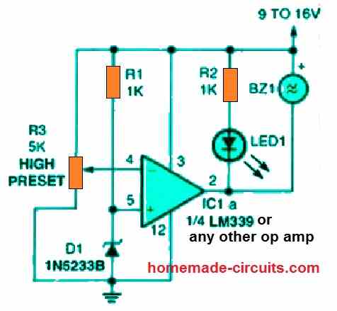
When the supply voltage exceeds a predefined level, this below given circuit generates a signal. The circuit is identical to the previous design except that the comparator's inputs have been inverted.
The output is kept high as long as the voltage at the comparator's negative input is lower than the voltage at the comparator's positive input.
The comparator's output becomes low when this situation is reversed, illuminating the LED and activating the piezo device. This battery over-voltage indication circuit could be a perfect match for any valuable type of hardware that works with a chargeable battery from an AC-operated source.
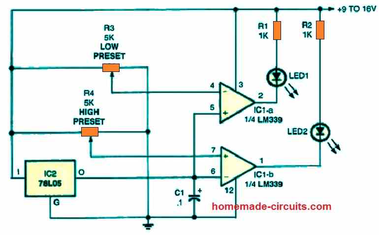
The first two op amp circuits are joined in the following figure to form a double voltage-monitoring circuitry. Whenever the supply voltage being checked is well within its predetermined limits, the LEDs in this circuit illuminate. IC1-a's circuitry is tuned to monitor the low-voltage level, whereas IC1-b's circuitry maintains track of the maximum voltage limit.
When the measured battery voltage falls below the lower threshold, the setting of potentiometer R3 turns off LED1, and when the voltage rises over the higher limit, the setting of potentiometer R4 turns off LED2.
Contrary to our previous two op amp circuits, the reference supply voltage Zener could be seen replaced by a single 78L05 IC 5 volt regulator. However, in this battery high/low dual voltage monitor circuit, a single Zener would also work instead of the 78L05 IC.




Questions & Answers
im glad to see you in this page good luck
My generator has a controller, when on auto I just need a dry relay contact to on the generator. That is when the battery voltage is around 30 or 40 percent the relay will switch on and the open dey contact on the relay will switch on the generator and when the battery is at 100 percent it should switch off the relay and the generator will go off.
You can find the required circuit design in the following link:
https://www.homemade-circuits.com/wp-content/uploads/2024/02/48V-battery-to-generator-relay-changeover-circuit-diagram.jpg
Hello boss, I have seen the circuit diagram you sent me. I have some questions to ask. What is the value of D3 and finding small 48volts relay from my area is slightly difficult, how do I convert the relay to either 12 or 24volt relay. Thanks
Hi Jolly,
D3 is an LED, if you cannot understand an LED symbol then how will you build this complex circuit successfully?
You can modify the circuit in the following manner for using a 12V relay.
https://www.homemade-circuits.com/wp-content/uploads/2024/02/48v-charger-circuit-with-relay.jpg
I will design the circuit soon and let you know.
I have a project for a 48volt battery monitor with a relay that will energize when the battery is low and will go off when the battery is full. I want to use the relay to start my generator when the battery is at a low range I will set and the relay should switch off when the battery is full
How will you use the relay to start the generator? Starting a generator requires a manual effort or a mechanical setup…
Hi, many thanks for a well written article. I have been trying to build exactly what you have described. A very basic question.. The first circuit, based on 4 x 6.8k registers and 4 x 10 potentiometers. Will that be the same values if fx measuring 10-12.5v or what that need some other calculations? I have tried to make it on bread board, but can’t really get it to work in the voltage range??.
Regard KT
Hi, I am glad you liked the post.
The first circuit can be used for any voltage between 5 V and 30 V. The presets work like voltage dividers and set the switch ON voltage limits at the non-inverting inputs of the op amps with reference to the 3.3V zener diode value.
When the non-inverting potential increases above the 3.3V value, the output of the relevant op amp becomes high and illuminates the LED. The presets are adjusted to set these switch ON limits for the op amps.
Many thanks for your reply, its really appreciated!! 🙂
I have just tried to build the circuit on a bread board several times. It still doesnt cope with with me, and I cant figure out why.
All the presents are working, as well do I get output on pin 1,7,8 and 14 when adjusting the presents. I have the circuit connected with a dimmer, and voltage goes to 12.3v.
When adjusting the voltage to e.g. 6v I adjust the #1 present, and #1 diode lights up. I change the voltage to 10v and adjust #2 present and #2 lights up, and #1 diode is off again. I power full up, and adjust #3 present and #3 diode ligths, #2 diode is off.
I think this is how I read the instructions…
But when slowly powering down the voltage, nothing happens – the different diodes doesnt turn off and on. Instead the last diode just dims off for finally to be off when voltage reaches 0. This doesnt seem to be right!!
Do you have a suggestion what it is I do wrong and I see this behaviour?
BR KT
Yes, all LEDs will not remain illuminated together, as the volatge is incresed, the lower LED will shut off and the upper LEDs will illuminate until only the top most LED is illuminated.
To understand the first circuit, you will have to understand its working.
As you can all are op amps and all the op amps are configured as comparators.
The idea is simple, the output LED will illuminate only when the (+) input of the opamps become higher than the (-) inputs.
The (-) input is referenced at 3.3 V.
That means, as soon as the (+) input pin voltages become higher than 3.3 V then the output LEDs will illuminate.
While increasing the supply voltage check the voltage values at the (+) inputs of the opamps, they should become higher than 3.3 V, only then the output LEDs will illuminate one after the other.
The (+) inputs are pin 3, 5, 10, 12. When voltage on these pins become higher than 3.3 V, the relevant LEDs will light up.
Hello, I sincerely hope that you are still watching this page. I am creating 2 – 12 volt lithium battery backed lamps. I am running the lamps off of a 600 mA plug in adapter. Each lamp has 2 – 3000 mAh battery packs. The operation is simple, when I loose power, a relay opens and supplies battery power to the single 12 volt / 60 watt lamp. These lamps only use 543 mA of power. I’m using the 600 mA adapter for each lamp because I read that these battery packs need to charge at 1/10 of their rating ((3000 mAh each X .1) X 2 batteries = 600 mA) I want to try to find a way to monitor these batteries and change a switch to allow the adapter to charge the batteries. Can this be done?
Hi, yes, definitely you can try one of these circuits to solve your application requirement.
Emmen, the Netherlands, july 22, 2021.
Dear Mr. Swagatam,
After a long search I came across your website. The circuit diagram with 4 leds appeals to me, because I want to make a battery tester that also uses 4 leds. For the record, I’m a complete nitwit when it comes to electronics, so it must remain simple and I have next to no knowledge of circuit diagrams, but working out a wiring diagram in practice is still possible. The battery tester that I want to make has to measure the condition of a battery pack consisting of 2 Li-ion batteries (each 3.7 Volt) that together provide 8.40 Volt fully charged.
By the way, I’m not doing this for myself, but for the Fietsersbond (the Dutch Bicycle Organization). Every autumn, it organizes days on which people can have their bicycle lights repaired by us, the volunteers. We do this for free, customers only have to pay for the parts and materials. And you can do this low budget organization a great service by adapting the Block Diagram for a battery tester that uses a battery pack of nominally 7.4 Volts (fully charged so 8.4 V). I would attach my overview and some photos of the repair days, but that seems impossible 🙁 I look forward to your much appreciated response!
Thank you Dear A.N. Bakkar, you can definitely use the 4rth circuit for the intended purpose! However, instead of using fixed resistors for R2—-R6, you may have to employ 1 k presets so that the LED illumination levels can be adjusted precisely for the corresponding voltage levels.
However, I would recommend the first circuit which gives a better control over the adjustments for the LEDs.
Thx, circuit favorited ))
Hello, I’m Christian and I would like to design a circuit that would allow me to power a sensitive 10A device in 12 Volts directly from a battery. The battery voltage can reach 14.8V so the circuit must limit the voltage to 13V maximum and must have a protection against polarity inversion and short circuits. I would also like to associate a led that flashes as soon as the battery drops below 11.5V and stops flashing after 12.5V (hysteresis). I have already done some research on LDO regulators but they are too limited because only 1A and zener circuits with ballast transistors don’t have any protection against short-circuits. For hysteresis and flashing I plan to use two NE555. Please I need your help.
Hello, you can probably try the second last circuit from the following article:
https://www.homemade-circuits.com/low-dropout-5v-12v-regulator-circuits-using-transistors/
Q1 can be replaced with a TIP36 transistor
Thank you
Dear sir,
I want to design battery level indicator for 48 volt battery with 5 led. Can you send circuit diagram, rating of components used and mathematical calculation
Dear Amit, you can easily use the first circuit from the above article, and add one more opamp for getting the 5 LED output.
Just make sure to connect the positive pin of the IC with a stabilized 12V, while the preset output may be connected with the 48V, preferably add a 10K resistor in series with each preset.
The presets and the 10K resistors will form a resistive divider and ensure that the sensing voltage at the input is kept well within 12V range.
All resistors will be 1/4 watt rated, opamps can be from any standard opamp IC
Hello sir Swagatam,
What modifications do I need to make to the above schematic (first one) so as to use it for both battery charging indicator and discharging indicator? I want to use it for both in a project.
Thanks in anticipation.
Hello Godson,
the first circuit will work for both, as a full charge indicator when the red LED lights up, and a full discharge indicator when all LEDs shut down except the white one which shows the last discharge level of the battery and indicates that the battery needs to be recharged immediately.
Green indicates battery is moderately charged.
Hello sir Swagatam,
Thanks a lot for the reply. What I actually meant was using the circuit when the LEDs are in the bar mode, i.e when battery is charging, the LEDs turn on one after the other until the last one is lit, meaning that the battery is fully charged, and when the battery is discharging, the LEDs go off one after another until the last one is turned off, meaning that the battery has discharged. Is it possible for the schematic to work that way?
Hi Godson,
It is possible by connecting the respective LED ends with the ground line instead of the opamp outputs…
Hello sir Swagatam,
Thanks a lot for the reply. According to the datasheet, LM324 has a maximum supply voltage of 32V. How do I use it on a 48V battery? What modifications do I need to make?
Please sir, could you suggest a schematic for 0-50V variable power supply. I am urgently in need of it. Thanks a lot in anticipation.
Hello Godson, you can regulate the positive supply pin of the IC with a 24V zener diode. Connect a 4k7 resistor from it Vcc to positive supply line, and a 24V zner from its Vcc pin to the negative line (ground line)
Link for the power supply
https://www.homemade-circuits.com/how-to-make-versatile-variable-voltage/
Sir i have few doubts…
* For 12v battery zener value 3.3
For 6v battery zener value ?
For 4v battery zener value ?
Pls tell sir….
Low voltage op amp ic also pls tell
sir
* 12v btry 7aH I’m using…if i give directly to IC +ve (pin no 4) voltage source.IC will be damage or i need to connect IN4007 diode ..to reduce the ampere for IC input (pin no 4)..
Kesav, it is not critical, you can use any value lower than the minimum threshold of the battery…the zener is only for providing a fixed reference based on which the presets are adjusted for the intended cut offs.
for low volatge operation it is better to use a BJT based circuit as given below:
https://www.homemade-circuits.com/2013/05/low-battery-indicator-circuit-using-two.html
the IC can tolerate upto 19v so 12V cannot be a problem, you can connect the batt directly, and a diode is not for reducing current, it’s job is to only block reverse voltage….
Thank u sir…
If u have LM3914 battery circuit sir…
I find many circuit not working proper sir…
Pls find me the good circuit sir…
You are welcome Kesav,
all circuits from this website will work but only if it’s done with proper understanding…if you do it without understanding then you will keep struggling even with the simplest of the circuits, ….and anyway electronics is all about understanding and implementing.
You can check the following design which uses LM3915
https://www.homemade-circuits.com/2013/08/3v-45v-6v-9v-12v-24v-automatic-battery.html
Hello sir Swagatam,
Thank you very much for this schematic. I’ll like to incorporate it in my inverter design. From what i see, it appears to be for 12V battery. If i want to use it for 24V, 36V, 48V, 60V and higher voltages (for higher inverter capacities), what part do i need to change? And please could you tell me the upper and lower threshold voltages for 24V, 36V, 48V, and 60V e.g upper and lower threshold voltage 12V are 14.5V and 10.5V respectively. Thank you sir.
Hello Godson, you can can easily use it for 24V monitoring also, just change the zener with a 6V or 9V zener diode. For higher than 30V, you can still use the same design but make sure the IC supply pins are supplied with a regulated 24V.
after this you can simply adjust the relevant presets for enabling the LED switch ON at the desired thresholds
Thank you for the prompt reply sir. When voltage is above 30V and i use a 24V regulator like you said, how will the circuit be able to monitor the fall in voltage since the circuit will keep getting a constant 24V?
the 24V should be separately fed only to the (+) supply pin of the IC, that is to pin#4 of IC LM324….
Very well then. So that means that R5 and P4 will now be connected to the positive terminal of the battery in question and the settings will be done. Thank you for the info sir. I want to design mine in a “bar graph” mode and use it to power off the inverter when the last LED turns off. Can i connect a 10K resistor from pin#1 of the IC to the base of an NPN transistor such that a relay-diode assembly will be connected between the collector and positive terminal and the emitter to ground, keeping R1 and the associated LED in their place and then use the relay contacts as the inverter switch?
Yes that’s correct R5/and the presets can remain connected with the battery voltage.
you can use pin#1 with a 10k/BC547/relay stage for initiating the mentioned operation.
Sir I need a circuit that can ON a fan if the temperature go up and switch OFF a fan if the temp go down.
Aminu, you can try the following concept
https://www.homemade-circuits.com/2016/08/incubator-temperature-controller.html
Secondly, can I replace the relay by connecting the emiter of PNP transistor to the Positive power of the IC SG3524?
So that, the inveter will shot down when the A4 LED gone off.
Aminu, it can be done, but as far as I know pin#10 of the SG3525 or 3524 requires a positive pulse for shutting down, not a negative pulse….you can do it as shown in the following diagram
2.bp.blogspot.com/-NSrqci3-b-8/U98ih86pV6I/AAAAAAAAH2E/i9tMa4nS-dA/s1600/sg3525+inverter+circuit.png
Sir, am building an inverter circuit using SG3524 IC.
So, My mind told me that, I can supply the Negative power to the inveter circuit through this LM324 by connecting A4 output of the LM324 to the negative supply to the SG3524. So that, the inverter will shut down if the final LED, that is A4 output short down.
Is this feaseble Sir?
I did it… It's quite simple.
My desing is in bar form and I'm operating 12v battery with it. What I need an addintion of relay to the last LED that will turn off together with the relay.
Thanks very much Sir.
Aminu, you can do it by connecting the base of a PNP transistor such as a BC557 with the output of A1…the relay can be attached across the collector and ground with a diode parallel to the coil.
also make sure to connect a 10k resistor between the base and the A1 output and a 4k7 resistor across base/emitter…emitter will connect with the positive line
Morning Sir,
I built this circuit since, and my design was working in bar LED mode. Now I want improve it by adding a relay in the last LED (that indicate below 11v level), so that if the last LED turn off relay will turn off too.
Sir how can I add a relay?
My mistake Mr.Majumdar, i meant to say lm339. It has all 4 opamps…
Thanks again.
yes LM339 can be used.