The post below discusses an automatic voltage analyzer circuit which can be used for understanding and verifying the output conditions of an AVR. The idea was requested by Mr. Abu-Hafss.
Technical Specifications
I want to make an analyzer for Automotive Voltage Regulator (AVR).
1. The three wires of the AVR are connected to the corresponding clips of the analyzer.
2. As soon as the analyzer is switched ON, it will apply 5 volts at INPUT and read the polarity at the output, C.
3. If the output is positive the analyzer should light up a green LED. And the voltage to be monitored across the C and B.
Alternatively:
If the output is negative the analyzer should light up a blue LED. And the voltage to be monitored across the A and C.
4. Then the analyzer should increase the voltage further at the input until the voltage at output drops to zero. As soon as the voltage drops to zero, the input voltage should be hold and the analyzer should display that voltage on a DVM.
6. That’s all.
Circuit Analysis In Details
The difference between an IC voltage regulator and an automotive voltage regulator. The latter is a transistor-based circuit and the former is an IC. Both have a preset cut-off voltage.
In an IC V/R, e.g. LM7812 the preset cut-off voltage is 12v. The output voltage increases with the input voltage as long as the input voltage is below the cut-off voltage. When the input voltage reaches the cut-off value, the output voltage does not exceed the cut-off voltage.
In an AVR, different models have different cut-off voltage. In our example, we consider it 14.4v. When the input voltage reaches/exceeds the cut-off voltage, the output voltage drops to zero volts.
The proposed analyzer has a built-in 30v power supply. Like an IC V/R, AVR also has three wire ---- INPUT, GROUND and OUTPUT. These wires are connected to the respective clips of the analyzer. Initially, the analyzer will supply 5v at the input and read the voltage at the output.
If the voltage at the output is almost same as the input, the analyzer will light-up the green LED indicating that the AVR circuit is PNP based.
The analyzer will increase the supply voltage at the input of AVR and monitor the output voltage across the OUTPUT (C) and GROUND (B). As soon as the output voltage drops to zero, the supply voltage is not increased further and that fixed voltage is displayed on the DVM.
If the voltage at the output is below 1v, the analyzer should light-up the blue LED indicating that the AVR circuit is NPN based.
The analyzer will increase the supply voltage at the input of AVR and monitor the output voltage across the OUTPUT (C) and GROUND (B). As soon as the output voltage shoots to 14.4, the supply voltage is not increased further and that fixed voltage is displayed on the DVM.
OR
If the voltage at the output is below 1v, the analyzer should light-up the blue LED indicating that the AVR circuit is NPN based.
The analyzer will increase the supply voltage at the input of AVR and monitor the output voltage across the INPUT (A) and OUTPUT (C).
As soon as the output voltage drops to zero, the supply voltage is not increased further and that fixed voltage is displayed on the DVM.
The Design
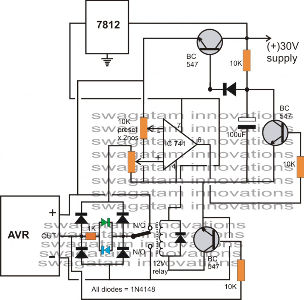
The circuit diagram of the proposed automatic voltage regulator (AVR) analyzer circuit is shown below:
When the input 30V power supply is switched ON, the 100uF capacitor slowly starts charging up producing a gradual increase of voltage at the base of the transistor which is configured as an emitter follower.
In response to this ramping voltage, the emitter of the transistor also generates a correspondingly increasing voltage from 0 towards 30V. This voltage is applied to the connected AVR.
In case the AVR is PNP, it's output produces a positive voltage which triggers the corresponding transistor, which in turn activates the attached relay.
The relay contacts instantly connects the appropriate polarity to the bridge network such that the ramping voltage from the bridge output is able to reach the opamps relevant input.
The above action also illuminates relevant LED for the required indications.
The opamp presets are adjusted such that as long as the output ramp stays slightly below than the input ramp, the opamp output stays at zero potential.
As per the internal setting of the AVR, its output would stops rising above a certain voltage, say at 14.4V, however since the input ramp would continue and tend to rise above this value, the opamp would instantly change its output state to positive.
With the above conditions the positive from the opamp fed to the shown transistor stage grounds the base of the ramp generator transistor, switching it OFF instantly.
However, during the above switching OFF procedure, the opamp quickly reverts to its original state bringing the circuit back to its previous state and the voltage appears to be latched at the AVR constant output.
The DVM must be connected across emitter of the top transistor and the common ground.
The 7812 IC is positioned for providing regulated voltage to the relay and the IC.
Circuit Diagram


Questions & Answers
Hello
I miss the electronic diagram of a Automatic Voltage Regulator AVR 0-110 V
it is used to excite the rotor generators
sadekmar86@yahoo.fr
Is what you can help me please
Hello, presently I do not have the design in my range, If possible I'll research some and try to update a suitable circuit for you.
By the way, referring to your advice of 28/08/13
"The transistor ramp can be paused by applying a positive potential to its base"
if positive potential is applied at the base of the transistor, the ramp output will become zero NOT paused. And when the base voltage is dropped to zero again, the ramp will re-start from zero.
When i said "paused" I actually meant "stopped", later on I realized the actual requirement and the issue….
yes it cannot be paused,
Hi Swagatam
Frankly, I got fed-up debugging this small circuit. To avoid further frustration, I simply assembled a fresh circuit with a minor change.
LM358 for upper IC, ramp generator
LM741 for lower IC, comparator
3.9V zener added between output of 741 and the LED assembly
Now the circuit is working perfectly.
Last but not least, thanks for non-stop and unconditional help.
Hi Abu-Hafss,
I can't figure it out, I think you should check it practically by assembling the parts on a veroboard, this would clear all doubts immediately.
Hi Swagatam
Thanks for your prompt response.
After thorough checking, I have some strange findings.
1. The op amp LM358 is working fine. When I separated the ramp section, I got ramp voltage from 5 to 31V.
2. When connected to 24V AVR it would ramp from 5 to about 20V only.
3. When connected to 12V AVR it would ramp from 5 to 31V.
4. I checked the 24V AVR with a variable power supply 0-30V, it worked perfectly, tripping at 28.8V.
Why would the 24V AVR not work with the ramp circuit? The only difference between the two is the values of R1 and D1.
Hi Abu-Hafss,
You can try TL07X series opamps, 1458, 4558…..however all might produce identical results, since all of them would be attributed with the same characteristics.
Hi Swagatam
I would like to refer this circuit once again:
The circuit operation was described in my post of August 26, 2013.
Recently, I had to use this tester to test a 24V AVR. For this the supply voltage to the upper IC has to be greater than the cut-off voltage (28.8V) therefore, I changed it to 32V. (LM358's maximum supply voltage is 32V).
However, the ramp I could get is 5V – 20V only whereas, when the supply voltage was 24V, the ramp was 5 to 23V. I checked LM358, GL358, and K*358, all have the same result. Quite interestingly, the simulator is also giving similar result, which leads me to conclusion that LM358 would not perform the job.
Could you please recommend me some other 8-pin (dual bcz of the PCB design) Op Amp (not comparator) which could handle 35V supply?
My pleasure Abu-Hafss.
Hi Swagatam
I am pleased with your approach of comparing my understanding with yours. Below, I try to explain the circuit:
When the circuit is powered on, the output of the upper op-amp (which is configured as an integrator) is constant 5V. These 5V are fed into the AVR and the output from the AVR (about 4.4V) are fed into the lower op-amp which is working as a comparator.
The Vref at the (+)ve input of the comparator is fixed at 1V. Since the output from the AVR is higher than the Vref, the output of the comparator is low. This low output keeps the PNP transistor ON.
Now, when the top switch is closed, 3V from the potential divider (right bottom) thru the PNP is fed into the integrator which gives out a ramp from 5V to 23V.
This ramp voltage is passed thru the AVR. When the ramp voltage reaches the cut-off voltage of the AVR, the output from the AVR drops to about 750mV. Since 750mV are lower than the Vref (1V), the output from the comparator becomes high (something less than 12V). This high output lights up the LED and switches off the PNP.
As the PNP stops conducting 3V to the integrator, the ramp is paused. And the paused ramp voltage (which is equal to the cut-off voltage) is read by a voltmeter.
Dear Abu-Hafss,
Remove the LED assembly and then check…..
Dear Swagatam
Thanks for the informative link about ramps.
I have practically checked number of times. I you like, I can send you a video clip of the results. Currently, I have two circuits in front of me, one on veroboard the other on a breadboard. The ramp section in both circuits are working fine. The ramp is pausing as and when required.
In fact, the entire circuit is working as desired till the input to the lower op-amp. Only the output is unexpected.
Hi Abu-Hafss,
I think the best way to confirm is to check it practically, this will allow you to analyze the stages separately.
Or alternatively you would want to study the following post to learn more about linear ramps and see if your design matches the calculations, because I am sure that the problem is in your ramp design.
http://www.ecircuitcenter.com/Circuits/op_tri_gen/op_tri_gen.htm
Hi Swagatam
The circuit is powered on with the switch opened. Thus the upper op-amp will output 5V to the AVR which will give output to the lower op-amp. And the op-amp's low output will switch on the PNP.
You know well, in an integrator circuit when Vin is smaller than the Vref, the ramp would be positive (upward) and if Vin is higher than the Vref, the ramp would be negative (downward). Disconnecting the Vin would pause the ramp and re-connecting would resume the ramp. You may try on a breadboard and check the results.
By the way, my problem mentioned on 25/08/13 is still unresolved.
Hi Abu-Hafss,
Everything in your circuit looks correct except during the initial situation when the power is switched ON and the PNP transistor switch is in OFF position.
How does the upper opamp react in this situation?
I think the PNP switch should be 2-way switch such that when it's in OFF position, the 33K end is kept grounded.
The transistor ramp can be paused by applying a positive potential to its base.
By the way both the counterparts cannot be paused at some selected desired level, both the ramps will not stop until they reach the supply voltage level….
Hi Swagatam
First of all, this circuit meant for testing only PNP type AVRs. The analyzer (discussed earlier) has its own importance for me and this tester has separate use.
Secondly, I thought of using your simple capacitor/transistor ramp generator but I could not work out a solution to pause the ramp.
Coming to your question; during the ramp, whenever the Vin is disconnected the op-amp and the feedback capacitor will make both inputs equal and the output is held (paused).
As mentioned earlier, in the circuit, when the ramp voltage reaches the cut-off value, the comparator switches off the PNP transistor which cuts off the Vin of the integrator circuit thereby pausing the ramp.
Lastly, I shall appreciate if you teach me how your capacitor/transistor ramp generator could be paused.
Hi Abu-Hafss
Please explain how and why according to you the upper opamp would start producing a ramp across it's output when the switch is pressed. I couldn't simulate it in my mind and that's why I wanted to know it from you.
In my diagram, the transistor ramp circuit can be easily simulated for the intended results, in the same manner I would like to know regarding the upper opamp working.
Hi Swagatam
Here is simple AVR tester circuit.
Theoretically and in simulators, this circuit works fine. But physically, I am facing troubles.
First, I used LM358 dual op-amp with 24v supply. The 1/2 op-amp generating ramp worked fine but the other half did not gave 12V with the calculated negative feedback resistor.
I switched to 2 x 741 but again the ramp generating op-amp worked fine and inverting amplifier did gave odd results which I had discussed with you on July 29, 2013 under AMPLIFIER CIRCUITS.
Then I used 2 separate LM358 ICs, as shown in the attached schematic. Once again, the inverting amp is not working as desired. I exchanged the IC but no difference. I checked the IC manually with same parameters on a breadboard, there the result was ok.
Your valued comments are requested, please.
Hi Abu-Hafss,
Please explain me the shown circuit by simulating it in your mind, I'll compare it with my understanding and tell you what might be the fault, I would like to know what you may be anticipating across the various stages.
Hi Swagatam
How can this blog be an interesting place without your spirit????
BHAI, MAKHIYAN TU WAHIN AAYEN GEE JAHAN PAR MEETHA HO GA!!!
I am bit concerned about the performance of your proposed analyzer circuit.
Firstly, as pointed out in my last post, the initial high output of the op-amp is preventing the ramp generation.
Secondly, even if something is done to resume the ramp, the behavior of the circuit against an NPN AVR is doubtful.
Our requirements for the circuit:
a) Ramp generation
b) I/Ramp at (+)ve input
c) O/Ramp slightly higher than I/Ramp at (-)ve input
d) Output to be low
PNP-AVR
=======
When ramp voltage reaches the cut-off voltage the O/Ramp will drop to less than 1V which will cause the op-amp output to go high, thereby stopping the ramp. And as you explained in the description, the circuit will go into a latch condition so we can get the cut-off voltage at the DVM……..YAHAN TAK THEEK HY.
NPN-AVR
=======
The O/Ramp will constantly be less than 1V until the ramp voltage reaches the cut-off voltage. However, the bridge will convert and supply
Ramp Voltage…….minus……. 0.6V (because of involvement of one diode from the bridge)
as O/Ramp. The presets are configured to maintain (-)ve input of op-amp slightly higher than (+)ve input which means low output.
Now, when the ramp reaches the cut-off voltage, the AVR output will shoot (from less than 1V) to 14.4V. But the bridge will shift and continue the O/ramp thru another diode. This means the (-)ve input remains higher than (+)ve thus keeping the output in low state. In simple words, when the cut-off voltage is reached no change will occur at the output of the op-amp. Hence, the ramp will not lock and the voltage could not be read at the DVM.
Hi Abu-Hafss,
Please do not recommend simulator results to me because for me these are like a "blind man with a stick" I don't trust them.
The opamp output can NEVER go high if its non-inverting pin is not higher than its inverting pin. So the idea is to keep the non-inverting pin low during power switch ON.
As I suggested earlier the best way is to analyze the stages individually and then compare by integrating them, it shouldn't take much time to troubleshoot by following this method.
Moreover the above circuit is pretty simple and practical troubleshooting should not take much time to accomplish, I believe:) It's a challenge to you, make it a success through practical trials.
Hi Swagatam
Definitely, you can rectify the issues………..you are a guru but, you won't make this useless (for you) circuit.
By the way, have you seen the simulation results?
There are 2 main issues:
1) The output of op-amp goes high at power ON.
2) The circuit is not giving results for NPN avr.
Haven't you got any hint from the simulation in the light of my earlier comments?
Hi Abu-Hafss,
I am sure if I make it someday would certainly rectify the issue whatever it may be, until then it would be difficult to say anything.
Hi Swagatam
The pin#3 is not going high when powered ON. Both, pin#2 and pin#3 are at 0V when powered ON. I clearly mentioned in my last post.
However, I have followed your suggestion but no change.
Here is the link for the simulation.
https://dl.dropboxusercontent.com/u/20969135/Analyzer%20link.txt
Copy the contents of the TXT file and paste it in the address bar of your browser.
To check PNP avr, S1=UP, S3=CLOSE, S4=OPEN
Since the output of op-amp is initially high, we disconnect it manually using S2. When the output goes low, S2 must be CLOSED. At cut-off, the circuit goes into loop and the I/Ramp remain constant…………THIS RESULT IS OKAY.
To check NPN avr, S1=DOWN, S3=OPEN, S4=CLOSE
S2 is kept OPEN. The ramp is OK. But the output of op-amp flickers on/off. If S2 is closed the ramp is paused and if kept open, we cannot get the results at cut-off.
Hi Abu-Hafss
Try introducing a delay network at pin#3. This can be done by connecting a 10K resistor in between pin#3 and it's preset connection, and by introducing a capacitor across pin#3 and ground. This will prevent pin#3 from going high during power switch ON. The capacitor value should be carefully chosen such that it just marginally delays the pin#3 operation.
Hi Swagatam
I have read the article repeatedly and have understood it. AB TU YAAD BHEE HO GAYA HY.
470uF is more than enough for debugging.
Theoretically, there was a minor mistake………the I/Ramp was connected to pin 2 and the O/Ramp to pin 3.
The presets are configured as mentioned in the article. When the system is powered on, pin 2 and pin 3 show 0V and the output high. For checking, I disconnected the output from the base of the transistor, the ramp becomes OK and the op-amp functions as desired. Even, the simulators also give exactly same results. This checking done only with a PNP AVR yet.
Next, as explained in details in my very last post I doubt the performance against an NPN AVR. Right now, I don't have one in hand to check. However, the simulation results also endorse my doubt.
Hi Abu-Hafs,
Thanks for your SWEET gesture:)
By the way did you read and grasp the explanation given in the article?
Please analyze the explanation and let me know theoretically do you find anything wrong in it?
If technically everything is correct in the given explanation, the circuit has to work.
You can slow down the ramp by increasing the capacitor to may be 2200uF, this will allow you to analyze everything cleanly….
Hi Swagatam
I assembled your proposed circuit with 470uF cap (for slower ramp). Connected 12V PNP AVR.
1) Green LED illuminated
2) Relayed did not clicked
3) Ramp voltage at emitter of top transistor was 3.4V
Then during my checking I blew up 7812, the output was showing same voltage as input. So I reduced the supply voltage to 16.5 which is within the operational range of 741 and also enough for checking a 12V AVR.
Now, the relay is switching on but the LED lights up only for a fraction of a second when the circuit is switched on or off.
Input Ramp (I/R) applied at (-)ve input
Output Ramp (O/R) applied at (+)ve input
FINDINGS:
I/R(-) O/R(+) OUTPUT
1.65V 1.75V 14.55V —> HIGH, not required
2.35V 2.25V 1.92V —> LOW, required
But, O/R is already lower than I/R and at cut-off voltage O/R will further reduce to less than 1V thereby the output remains low which will not give the desired results. Therefore, I interchanged the inputs in the circuit and here are the findings:
O/R(-) I/R(+) OUTPUT
2.30V 2.25V 1.92V —> LOW
Ramp Voltage 3.4V
Though we are getting the desired low output but 1.92V are quite enough to switch on the transistor which is giving incorrect results. I replaced the IC 741 with a new one but no change.
Now, what shall I do?
Hi Abu Hafss,
as explained earlier, the opamp output will become high only if voltage at pin3 is higher than pin2.
You should adjust the presets such that pin3 is fixed at slightly lower voltage than pin2…. and pin3 should be connected to the emitter follower output while pin2 to the AVR output
Hi Swagatam
As per your guidance, I started checking stage by stage and found the emitter follower transistor to be the culprit which was giving constant 3.4V at the emitter. After replacing it, got a perfect ramp at the emitter.
After integrating the ramp with rest of the circuit, as soon as the circuit is powered on the output of the op-amp becomes high which switches on the transistor and ultimately prevents the ramp. No ramp means no voltages at both the inputs of the op amp. Hence, the circuit comes to a halt.
No idea about the ICs, checked it online but couldn't find it.
that's correct friend.
I salute all the readers like you for making this blog an interesting place
Can you please tell me what is this IC?
I cannot find IDEA9104 or YY0550 anywhere. Is it some custom-made special purpose IC.
Hi Swagatam
SAB CHALTA HY, BAAT SAMAJH AANI CHAHIYE !!!
Anyway, salute to your spirit of sparing time to help/guide others.
…sorry too many grammatical mistakes in the above comment.. wrote in a hurry..
Hi Abu-Hafss,
It depends on the particular IC, some produce less offset voltage and produce a little more, so adding a zener is the only soution or you add an offset null preset to overcome.
According to me the circuit should work as expected because I cannot see anything doubtful in it, but without practically seeing your circuit would be difficult to troubleshoot. May be you can make the stages separately and test each stage them by manual enforcement and then integrated them to see the final result.
Hi Swagatam
I had that JUGAAR solution in my mind but I was thinking that 1.92V is incorrect output. Just for learning sake, can you explain how we get 1.92V?
And what about the LED, why it is not lighting up now?
Hi Abu-Hafss,
Use a zener diode in series with the output of the opamp, a 5.1V zener will do the job, this will prevent the leakage voltage from entering the transistor base.