A rather cheap yet reasonably effective short circuit protection circuit is I have explained below which can be used for safeguarding power supply circuit
Introduction
A power supply unit is an indispensable unit for every electronic enthusiast and engineers working in the relevant field. Though today all of us use hi-tech power supply units having built-in protection, there are folks who still rely on ordinary types of power supply units with no protection facility.
The biggest enemy of all power supply units is a possible short circuit that might occur at its output terminals due to an accidental connection or due to the fault with the connected load.
There are various electronic circuits that might be employed with a power supply unit for checking this problem, however these circuits sometimes themselves are at risk of getting damaged due to the limitations with many electrical parameters.
A very innovative way of rectifying this problem has been shown in this article. A single relay is used for sensing as well as tripping the output from the involved malfunction.
Circuit Operation
Referring the circuit diagram, we see that a relay is connected directly to the output of the power supply DC output, however the connection is made through the N/O contacts of the relay. These contacts are also terminated as the output of the unit.
N/O means normally open, that means the contacts are open initially, which in turn keeps the output disconnected from the positive of the power supply.
Now when the shown push button is momentarily pushed, the N/O contacts are bypassed allowing the current to flow across the relay coil.
The relay coil energizes, closing the N/O contacts, which in turn latches and sticks to the position even after the push button is released.
The relay latch maintains this latched position as long as the output is used under normal conditions, but in an event of a short circuit across the output terminals, there may be a sharp drop in voltage, the instant this voltage drops below the coil voltage of the relay, it loses its holding strength and immediately releases the contacts, and trips, cutting OFF the supply to the output and in the course switches OFF the latch preventing the short hazard conditions.
This brings the relay to its initial condition and needs resetting in order to restore power at the output.
The circuit diagram for the power supply short circuit protection is shown below:
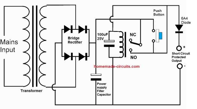
Power Supply Short Circuit Protection using SCR and Relay
The next circuit is another over current protected power supply circuit which employs an SCR and a relay for the required protection and cut-off.
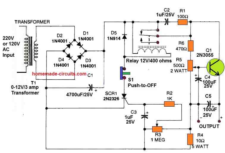
It's basic yet efficient in managing up to 24 VDC. The maximum voltage output may depend on the secondary voltage of the transformer. With the help of the 500-ohm potentiometer, the output voltage could be changed.
As soon as the protecting circuit detects an upsurge in current, the SCR will activate the relay coil, shutting the load's power and placing the circuit in idle mode. S1 should be pressed to deactivate the SCR once the over current issue has been fixed.
The 2N3055 transistor works like the voltage regulator pass transistor. However, this transistor section could be entirely replaced with any other standard voltage regulator IC such as LM317.
The 1-megohm variable resistor can be used to control the sensitivity of this SCR protection circuit.
Short Circuit Protection for Variable Power Supply Circuit
If you are having a variable power supply and want the short circuit operation to work even at voltages below 3 V or 1.5 V, then you can try adding the following short circuit protection circuit to your power supply circuit.
The idea was designed and submitted by one of the avid readers of this blog.
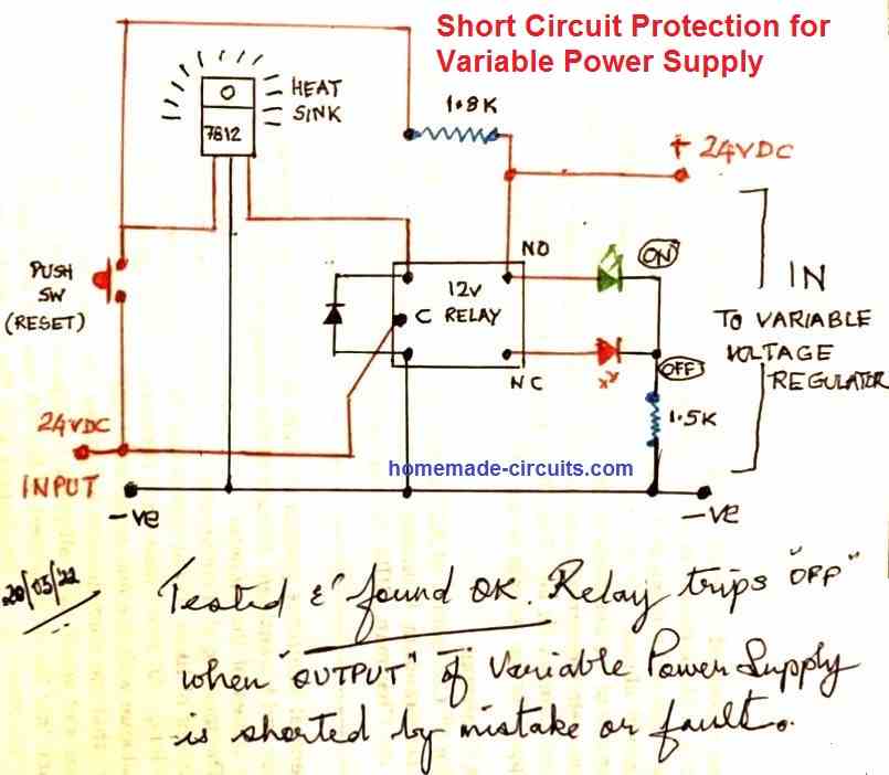
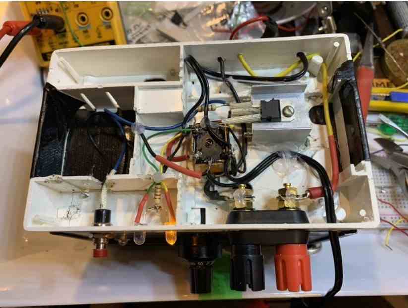
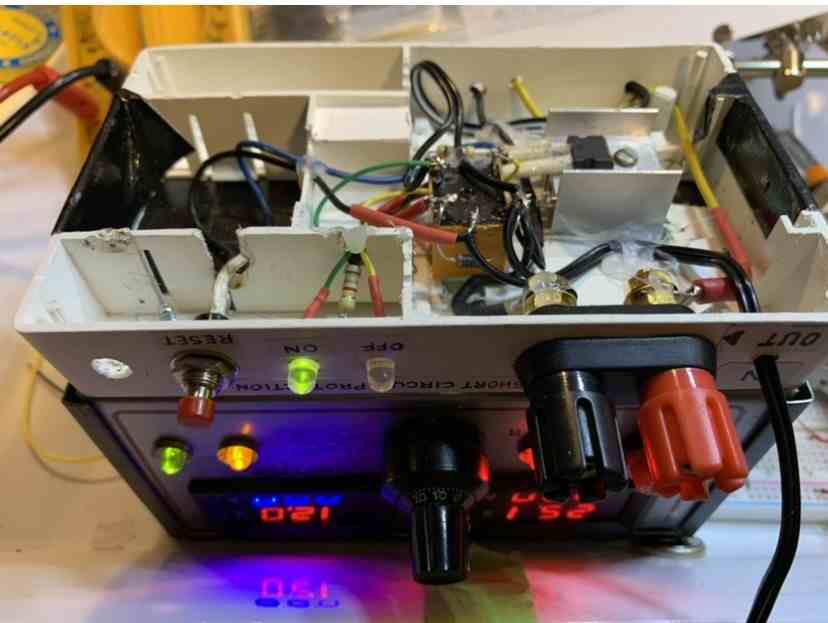
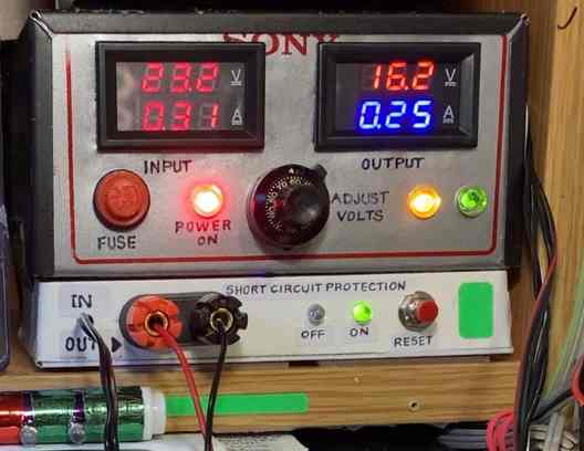
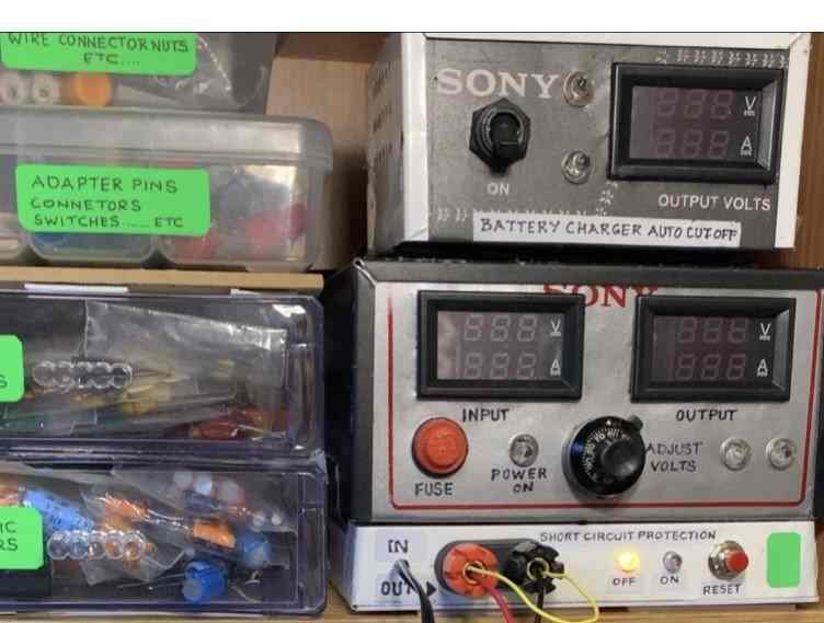
The above was tested and found to be working satisfactorily. The images show how the circuit was practically implemented into a variable power supply unit.



Questions & Answers
Hi,
Can the short circuit protection using relay work with a SMPS? I was not sure if the SMPS output voltage would drop sufficiently in time (before the load is fried) for the relay coil to demagnetize. I thought the SMPS would not drop its output voltage till it’s current limit is reached. In my case the current limit is too high.
I was considering building the “Short Circuit Protection for Variable Power Supply Circuit” for loads using a Meanwell 12V SMPS.
Thanks for your great work.
Your assumption is right, it won’t help with SMPS designs. So it is better to configure a current limiter inside the SMPS, possibly at the source pin of the power MOSFET of the SMPS oscillator.
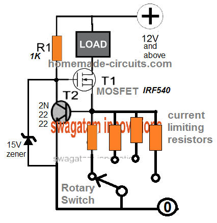
Alternatively, you can also consider a current limiter circuit externally at the output of the SMPS, such as this one:
Thanks. I think I’ll consider putting a buck converter with adjustable current limit after the SMPS to be reasonably efficient. I think I can bump up the SMPS output to 12.7V to compensate any loss due to the buck converter.
Sounds good, probably the XL4015 5A DC-DC Step Down Adjustable Power Supply Buck Module might do the job…
Yes, you’re right. Thanks!
Hello, do you know any Short Circuit Protection for Variable dual (simetric) Power Supply?Thank you
Hello, I will need to see the schematic to suggest a possible protection circuit.
Thank you for your reply. If you please, take a look at the schematic of my simetric power supply. i need help for creating a short circuit protection. Thank you.
https://drive.google.com/file/d/1ziIz8BmFbfvUCVRtxKwDbViO3EUqwR1T/view?usp=sharing
No problem Maia, I checked your schematic, it looks similar to the concept explained in the following article. You can incorporate the current limiting feature provided in this article:
https://www.homemade-circuits.com/0-to-50v-0-to10amp-variable-dual-power/
Why is the 1.8K Ohm resistor needed
It causes the circuit to latch so that the 7812 and the relay remains powered even after the push button is released.
Hello, I’ve created a short-circuit protection relay circuit, but instead of using the 7812 integrated circuit, I used a 24-volt relay directly. Initially, it worked flawlessly. My power supply is 19 volts AC. After converting it to DC, the voltage becomes 23-24 volts DC. When the AC voltage rises to 20-21 volts, the DC voltage becomes 25 volts or higher, and the short-circuit protection stops working. The LM317 TO3 transistor becomes unusable during a short circuit. What should I do?
Hello Koray,
I will need to see your circuit diagram to understand its design and only then I can provide you with a solution…
I built the above circuit, and it works flawlessly. I can use it with a maximum load of 4A.
I built the circuit shown on your page as a short-circuit protection system. It worked flawlessly, but when the voltage increases, the short-circuit protection stops and the relay doesn’t disconnect.
That is a LM317 power supply using an outboard BJT for current boost.
You can add a current limiting feature simply by inserting a calculated resistor in series with the emitter of the PNP BJT.
For more info you can read the following article:
https://www.homemade-circuits.com/lm317-with-outboard-current-boost/
Thank you very much for your interest. Is there any way I can use the relay circuit described in this article?
The relay circuit explained above is a very crude way of adding a short circuit, I won’t recommend it… better to add an extra BJT with the existing PNP for efficient current limiting using smaller sensing resistor or add an emitter series sensing resistor, which can be relatively larger in size..
thanks
Hello, just add 2 diodes “1n4007” before LEDs. At the beginning, circuit has output voltage. so with these diodes we have zero volt in circuit’s preset.
Thank you for the suggestion. Appreciate it!
Have a nice day bro. I made a spms circuit that produces a constant output of 74 volts from the voltage I get from your 220 volt network. What can I do to protect my mosfets in my circuit from overcurrent. I trigger my mosfets with a pwm signal. I do this triggering with 3 trigger transformers. I have a 25 khz voltage reducing transformer. How do I make a short circuit for this spm circuit. I am waiting for your help. Thank you in advance.
Hello, have you used any IC based controller in the SMPS, if yes then you can put a series resistor with the MOSFET source, and use the voltage drop across this resistor with the shut down pin of the IC, during an over current.
Please how can I extrapolate this circuit to work for shut down pin on inverter module.
Which IC are you using for the inverter?
Sg3524 Ic
You can refer to the following post and see how the feedback for the over voltage and over current are included in it: Over voltage cut off at pin1, over current cut off at pin4/5
https://www.homemade-circuits.com/inverter-circuit-with-feedback-control/
Please how can this circuit work for AC power supply, it is not clear to me, Sir
No, This is recommended only for low-power power supplies…
What should be the value of the 2 capacitors in the input for the regulated power supply.
left side is 1000uF, right is 220uF
Is there a solution with a transistor to protect the relay coil in case of hight current , and adjustable to set at which amperage the relay cut off !?
relay coil will not get affected with high current, rather it is a high voltage that can damage it. So if the voltage is constant, current won’t matter.
i must admit this took longer than it should have for me to understand, it’s quite a neat idea, but you said “there may be a voltage drop” so what happens if there isn’t one ? like if i’m using a constant voltage power supply ? also what if the voltage drop is not enough ? for example a 12v relay still works at 9.8v (don’t know where it stops) and i’m guessing this doesn’t work at all in a variable power supply.
Also your relay has to match the voltage output of the power supply, do they make relays that work on 5v ? or 19v ? i’m guessing you are limited to the common ones, like 12v.
Whether it’s a constant voltage or whatever, when there’s a short circuit the supply will drop rapidly towards zero V, and the moment it drops below the holding voltage of the relay, it will trip…so it’s a fool proof design.
This circuit will work for variable power supplies also, you just have to add the variable circuitry at the “load” side of the design.
I hope that clears the doubts.
HI swagatam… i tested this one with 5V relay … it works perfectly when i am using this circuit with normal 5V 2A smps but when i am using this circuit with 5V 60A smps it does not work. i got just big spark when circuit shorts but relay doesn’t trip. what should i do
Hi Manish, to work with 60 amps the relay contact must be rated at 100 amps, otherwise the relay contact will fuse instantly when the output is shorted.
cool, thank you for the quick reply, are the 2 capacitors part of the rectifying circuit or are they for the relay somehow ? if the later, what values would you use for a 12v power supply ?
The reason i landed on this page was because i was looking for a way to protect my power supply from shorting out because i’m trying to power a reversible DC motor with 2 relays to switch polarity, but if both relays are switched on at the same time by accident they would short the power supply. And because of your design i got the idea that maybe i can cut of the power of one relay while the other one is powered (with the 1st relay), i’m gonna pass the negative of the signal of the 2nd relay through the NC pin of the first (and vice versa), so when one is on the 2nd one cannot turn on, not sure if that will work.
If you use a DPDT relay method, there won’t be any chance of a short circuit as both the contacts would switch together in this case, for the required bidirectional movement.
yeah, in the end i figured that out as well, it’s just that i was also using the relays to turn the motor on and off (this is for my new front gate that i am automating), so the motor going endlessly in one direction or another was not a good thing, but then i remembered that i was gonna install limit switches anyway, so i’ll just use those to turn the motor off at the right time.
Question: can a relay stay on (latch) forever without breaking ? i’m gonna use the NC loop/side of the relay to close the gate to avoid the relay staying on for a long time.
yeah, i know, i saw some say they have silver and such, but i wasn’t asking about the contacts, i was asking about the thing that makes the contacts move.
A relay basically is an electromagnet with a spring loaded magnetic shaft operated by the electromagnet, you can get more details below:
https://www.homemade-circuits.com/how-a-relay-works-in-circuits-how-to-connect-it/
by ‘latched’ i meant ‘powered on’ not fused shut, so i was wondering if the device that powers the relays contacts can get worn out for staying on to long, i presume it’s an electromagnet and a spring.
I’m using a windshield wiper motor (12v@5A) that i think i might be powering with a variable voltage circuit (so i can adjust the speed) that has a constant current function, so i don’t think i will be needing that current limiter, but thanks for the link anyway.
The contacts are coated with special alloys so they are usually very resilient to all forms of wear and tear….
A relay can get latched typically due to fusing of the contacts, in case the contacts are subjected to higher current than the rated specs. The best way to avoid this is to add a current control stage in between the contacts and the load. A few simple current control stages are explained in the following article which can be tried:
https://www.homemade-circuits.com/universal-high-watt-led-current-limiter/
Olá Swagatam,
Este circuito suporta 50v 10A, ou quais modificacoes devo fazer?
Poderia postar circuito de fonte 50v 10A, quando regulada para 10A a tensao nao cair ou seja estabilizada.
Hi Joao, yes you can use it for 50V 10amp, just add a small value resistor in series with the relay coil, may be a 22 ohm… and make sure the contacts are rated at 20 amps or 15 amps minimum.
Hai sir….*
I tried this circuit it’s working well…
I have one adapter type smps…
O/p 12v 1.5A …
Its working good…This smps contains short circuit protection…
If i short it…smps power led goes OFF…if i un short it…smps power led ON…
I can’t able to find the circuit diagram…fully molded …
So pls guide me sir…
Is there any circuit same like…
Whenever short happen….smps power led off and in normal condition smps power led ON….
Pls guide me sir….*
Thank u sir
I need Circuit diagram sir….
Kesav, you can refer to the following article for all the details:
https://www.homemade-circuits.com/2015/04/how-to-make-variable-current-smps.html
Hi Kesav, it is normally done through a current sensing resistor at the output side of the SMPS, when current exceeds across this resistor, the feedback optocoupler gets activated which switches OFF the primary side of the smps preventing the short circuit
Thanks for your suggestion bro, multimeter power supply 9v by adding capacitor in output is not working on my cheap meter . cell phone charger idea help little bit that is while touching the negative by hand gives proper reading , finally I decided to leave on battery power supply with on/off using relay (one COB multimeter gets defective while measuring voltage more than 3v) . thank you …
OK, thanks bro, keep up the good work!
Hai Bro, your help please .
three dc source with one voltmeter, I need a circuit to measuring voltage of dc source ( common ground) by selecting with one push switch ( 3 way sequential selector switch ) using relay , thank you
Hai bro sorry for disturbing you again and again , I thank you once again for your quick response, I tried sequential push selector switch it works perfect but some delay in selection ,then i changed the capacitor between pin 13 &14 with 0.5uf instead of 1uf it works charmingly thank you ..
I made variable PSU using lm338t plastic package t220 , when output get shorted ic gets heated instantly with in 4 sec ic gets damaged in min/max output ( but using lm317t long term short circuit and work absolutely perfect without ic gets damage ) even though using proper huge heat sink and fan ,please provide any short circuit protection circuit for variable psu ( but while using lm338k its works fine for some limits time approx 1 to 4 mins , I tried your electronic fuse works perfectly for constant voltage 5 to 33v thank you…
Bro, LM338 is the 5 amp version of the LM317…and both these ICs are thoroughly protected from overheat and overload situations…..if your LM338 is burning due to overheat that means it is a duplicate IC not original make.
short circuit protection is absolutely not required for these ICs…you can check the details in the datasheet of the IC.
bro, you can try the following concept:
https://www.homemade-circuits.com/2013/08/single-push-10-step-selector-switch.html
Sir
I made your short circuit protection circuit it works fine for transformer power supply , if I connect to battery 24v 10Ah ,circuit not working ( when shorting output voitage across relay not fall to zero ,instead huge spark and melting wires) please give any modification or new circuit.sorry for my bad english
Deepak, it’s because a transformer has limited current which is able to drop, whereas a battery may have relatively huge current which may not drop quickly causing melting of wire.
add a current limiter in series with the battery, and you will find the system working perfectly. You can do this by adding a low value resistor such as a 2 ohm 5 watt etc or you can calculate it using Ohm’s law
alternatively you can try the following design which is designed for battery use
https://www.homemade-circuits.com/2012/04/how-to-make-automotive-electronic-fuse.html
Thanks Bro, I made your new electronic automotive fuse it works fine,one again thank you for your fast response, I made another circuit 24v battery to 12v 200mA circuit using lm317 adjustable but lc get heated ( some power loss approx 3w as heat) please give any efficent simple circuit for 12v 200mA, thank you.
My pleasure mate, if you are using any linear IC then it will waste a significant amount of power..there’s no way to avoid this, unless you upgrade it into a buck topology as explained in the following article, you can try it out:
https://www.homemade-circuits.com/2016/10/lm317-variable-switch-mode-power-supply.html
Bro another help please, I want to add cheap multimeter ( 2$) as voltmeter for my variable power supply unit , multimeter is 9v battery powered ,I replace it by 7809 ic but while measuring (i.e self powered multimeter) improper reading , please give any simple isolated power source circuit 9v or any suggestion/ideas thank you…
sure bro, the 7809 should have worked correctly according to me, first confirm whether or not it is giving an accurate 9V without the meter connected…if it is fine, then you can try connecting a high value capacitor across the output and ground of the 7809 and see if that correts the issue….you can try a 1000uF/16V or even higher. alternatively you an simply use your cellphone charger output and use it for powering the meter, it worked great in my meter.
Thank you for suggestion Bro. ….
Hi sanjay bharvad,
I believe it is possible if you have a step down transformer if it is 50-100HZ ac or high frequency circuit which will step down the 9kv to easy to manage power like 12v. you can then utilize the relay powering circuit from 12v external source and use zener diode to cut out form a cut-off point when the 12v which is directly influenced by the 9kv fluctuates to the level you may want a shut down.
I have utilized similar circuits in lithium ion short circuit controls for electric cars.
Hello sir ..
I want to operate 12vdc relay by short circuit 9000 vdc ..please inform me can I use this circuit..for that and which type of changes I have to do
Hello Sanjay,
I don't know how you would configure 9kV with a 12v relay, I think that's not possible with the above circuit.
hello sir as u said above "could be used in variable power supply unite. ." how does relay going to react in case of low voltage is being set eg: 12max out put relay set to 12vminmum if turn down voltage to 2v then I hope relay going to be Delatch .? right sir ?
Thank you in advance
Yes it will, that's the main purpose of the design
Thank you for replying sir..
but does it supports my 1st conditions
I.e 1)Disconnect input after (set) full charge.
if not what simply modifications may required ?
plz let me know
thank you..
you can try the second circuit from the following link:
https://www.homemade-circuits.com/2011/12/how-to-make-simple-low-battery-voltage.html
for 3V battery replace 741 opamp with some other opam which can work with 3V, and also replace the 4.7V zener with 3 1N4148 diodes in series in the opposite polarity to the zener
Thank you for replying. ..
plz also let me know the simple circuit which can be used to charge 24/12/9/3vDC battery ..
(based one preset settings .. )
with minimum below options or better then this.:
1)Disconnect input after (set) full charge.
2)Disconnect output after (set) minimum level. to avoid Deep discharge
I have already posted this circuit, here's the link:
https://www.homemade-circuits.com/2015/10/smart-emergency-lamp-circuit-with.html
Yes something like this I was looking for thank you sir.. just need to find what the value for 230v 45 w that's ok I will tryout..
and also let me know. ..
So eagerly waiting for circuit which will be having following (few or all) features -Low Battery Cut-off
– Overloading protection
– Short Circuit protection
– Reverse current protection
– Reverse polarity protection
– Thunder protection
– Over discharge protection
– Auto battery shut-off at Low voltage detection
– Overcharge protection
– Auto charge stop/ High Volt Detection
– Battery capacity level display(SOC)
Making this circuit for underprivileged location as donation for poor via charity So hope I can have one ckt diagram with some or all features mentioned above or lts link.. Looking for ur reply ..
With full excitement
Thank you
Regards
Lokesh
If successful I am in plan to put ur & website name on my device As part of tribute to you sir
you can try the C1/C2/L1 configuration as shown in the following diagram, and see if that helps:
4.bp.blogspot.com/-khKat0UA8Jw/UITpCnNd7yI/AAAAAAAAA_A/8x-KAD2aHLE/s1600/simplest60+Hz+Inverter+circuit+diagram.jpg
Thank you for replying sir.. I have checked the link. .. and I feel that circuit is made for building newly. .but I am looking for circuit which can be added at the end of square wave 230v 45w inverter. . which is presently not supporting any Transformer and capacitive step down type load.. due to square wave out put.. hence I was looking for minimal change in inverter so that I can run above mentioned load too..
hope my msg is convinced. ..
Thank you
you can refer to the following post for learning more regarding how to modify square to PWM sine waveform:
https://www.homemade-circuits.com/2013/04/how-to-modify-square-wave-inverter-into.html
ok I will try sir..Thank you for ur efforts to support me..
also let me how can I prepare an
"Add on circuit " for converting
square wave out put of 230v to sine wave ?
would you take the risk of accessing the shut down pin of any of those ICs and link it with an external circuit? if not then it's better to go for a linear current limiter circuit at the input, as shown below:
https://www.homemade-circuits.com/2013/06/universal-high-watt-led-current-limiter.html
ho nice.. but I am using ready kit bought from ebay if u type
"(LM2577S + LM2596S dual chip modules, DC-DC step up step down module )"
u may get it.. sir in ebay website hope u get an idea about it.. since I am not confirm that's y worried. . hope I can get solution as soon as possible. . 🙂
Lokesh, if you have planned to use a LM2596S circuit then a better and more logical idea would be to use its pin5 for the overload shut down…the above relay method would be too crude for this.
If possible I'll try to post the whole idea soon in my blog.
Thank you for replying sir..
actually I am planning to put buck boost converter
(LM2577S + LM2596S dual chip modules, DC-DC step up step down module )
… Instead of 78xx since its too hot to handle. .
ok as u said if I connect this system before
buck boost module. .. does it functions same.?
and more querie does the buck boost module support short circuit cut off.?
Hello Lokesh, the variable supply stage will need to be after the relay, meaning the relay contacts will be supplying the variable circuit stage, and the output from the variable circuit supply will finally reach the load.
The relay stage will be associated with the bridge rectifier, and the relay coil will need to be rated as per the bridge output voltage
Hi Swagatham
Can you publish an LM317 based 1.25V to 24V, 5A variable powersupply circuit. I know 317 can only handle 1.5A, so a power transistor(s) can be used to handle current more than 1.5A.
But I don't want that bulky power transistor. I prefer an N-Channel power mosfet for enhansing LM317's current capacity. Is it possible….?
I searched google for such a circuit, not yet found. If you can add output SHORT CIRCUIT PROTECTION, with latching/auto reset after removing short circuit. That will be an added advantage.
hi Anil Kumar. K
if possible check this by copy pasting below
"LM2577S + LM2596S dual chip modules, DC-DC step up step down module "
in ebay.in hope ur requirement gona match
Hi, Anil,
although a BJT looks more appropriate as the outboard current booster device since it requires just 0.7V to trigger, let's try this with a mosfet and see how it responds…I'll design and post it soon.
hi swagatam, can you please guide me what component and value should replace in diagram i want to make an variable resistor which is 30v is the max output by using an 24v 6amp transformer
edde
hi swagatam
can you please guide me i would like to make a variable resistor, which component should i replace and value? i already have transformer which is 24v 6amp. thanks advance
Ho Gary, did you mean a variable voltage power supply? please clarify.
hi swaggatam, how do you make a circuit like above to short circuit protect a lithium bank of 200v?
Im working on a project and i noted that an accidental increase in current draw would lead to fires,
…C1 must also be removed, and R6 replaced with a 10K 5 watt resistor
Hi Joshua, you could try the following concept:
https://www.homemade-circuits.com/2011/12/how-to-make-mains-av-short-circuit.html
remove the triac/R4, and replace R3 with a relay coil, the relay contacts can be then wired with the load in series with the 200V battery supply.
The indicated mains input gets replaced with the 200V input
hi again,
Thanks for your responses 🙂
As I said before, I'm placing this circuit after a voltage regulator. The problem now is that when I regulate the voltage to lower than 3.5 volts, the relay opens, so I cant use lower voltages than that. The reason why this appens is quite obvious, I just wanted to ask if you have any suggestion on how to solve it.
By the way.. have you thought of this circuit as being one bit of digital memory?
In my prototype the relay was making a lot of noise while switching off while I was testing it with an output short, ……….adding the capacitor instantly solved the chattering issue therefore I had to include the capacitor in parallel with the relay coil.
Following your advice and the instructions given on http://www.ikalogic.com/bjt-switches/ , I've built the following circuit:
It works! Although I had to eliminate the capacitor because it wasn't allowing the relay to switch off… I didnt understand why…
Please give-me your feedback, i'm not sure if I'm doing what you had in mind.
Thanks for your help!
Regards, Daniel
Hi Daniel, it's a crude circuit for achieving a short circuit control, it can be easily modified for a better response by just adding a BJT with it, i'll try to update it soon…this modification will allow volatge inputs below 1 V.
yes most latch circuits could be considered as a 1 bit memory circuit…
Hi Swagatam! I've built the circuit and it works great! thanks!
I just have two questions:
1 ) is the diode really needed? what is it for? having it means that I will always have a 0.7 voltage drop and I would like to avoid it because i'm puting the circuit after a previously regulated power supply.
2 ) Is it safe to use this circuit as a short circuit "detector" to repeatedly check solderings, etc. (as I usually do with the buzzer in my multimeter)
Thanks Daniel,
The diode can be removed.
this circuit is a crude design and will work only for high current short circuit scenarios….it's not suitable for detecting low current soldering faults.
Hi Swagatam, Is there a way to use this circuit for a variable power supply ? What modifications will be needed ?
Hi Janesh, No modifications would be required, just connect the variable power supply circuit with the output of the above shown design
sir, does it resets automatically or we should do something for it to have a reset function?
No it won't, you will have to press the push button to reset it back into action. There's no automatic option for this simple design.
connect another LED across relay N/C and ground via 1K resistor.
The DC comes from the AC after all. So the AC control will be directly proportional to the DC.
Anyway with a 337 IC you can do the following:
use a BC557 transistor.
connect collector to ADJ, emitter to ground-relative to (-).
connect base to ground via a 100 ohms and put another resistor between the emitter ground connection and base ground connection…meaning the emitter/ground joint and base/ground joint must be bridged with a resistor.
This resistor decides the current limit.
find it by using R = 0.6/limit current = Ohms.
you can put it anywhere you like, before or after the regulator….it will do its job as specified.
by the way if you are using a 78XX regulator then you probably wouldn't need the above arrangement because all modern regulator have built-in short circuit protection and are litrally blow-out proof
you can try this circuit, it will provide both over current and short circuit protections for the transformer.
https://www.homemade-circuits.com/2013/07/simple-ac-mains-short-circuit-protector.html
Thanks! Relay voltage should always match the supply voltage, therefore for 27V the relay should be rated at 24V.