Among the different existing inverter topologies, the full bridge or the H-bridge inverter topology is considered to be the most efficient and effective. Configuring a full bridge topology could involve too many criticality, however with the advent of full bridge driver ICs these have now become one of the simplest inverters one can build.
What's a Full-Bridge Topology
A full bridge inverter also called an H-bridge inverter, is the most efficient inverter topology which work two wire transformers for delivering the required push-pull oscillating current into the primary. This avoids the use of a 3-wire center tapped transformer which are not very efficient due to their twice the amount of primary winding than a 2-wire transformer
This feature allows the use of smaller transformers and get more power outputs at the same time.Today due to the easy availability of full bridge driver ICs things have become utterly simple and making a full bridge inverter circuit at home has become a kids play.
Here I have explained a full bridge inverter circuit using the full bridge driver IC IRS2453(1)D from International Rectifiers.
The mentioned chip is an outstanding full bridge driver IC as it single handedly takes care of all the major criticality involved with H-bridge topologies through its advanced in-built circuitry.
The assembler simply needs to connect a few handful of components externally for achieving a full fledged, working H-bridge inverter.
The simplicity of the design is evident from the diagram shown below:
Circuit Operation
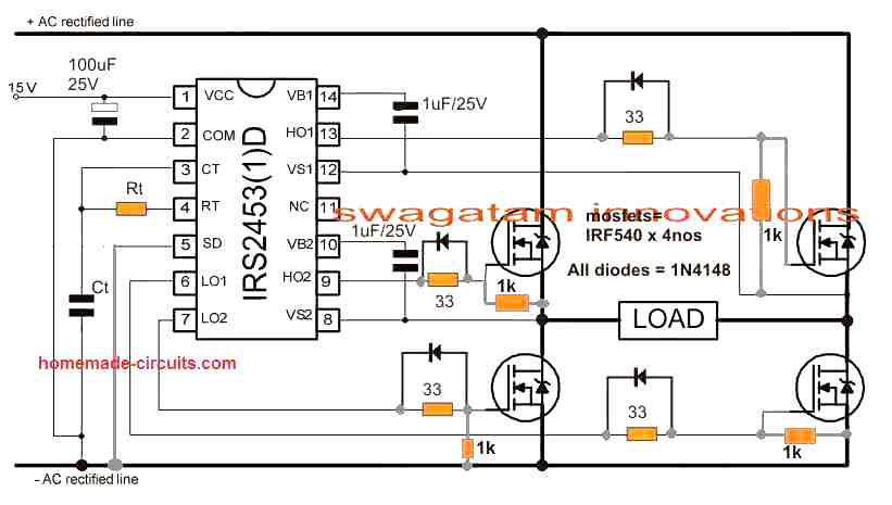
NOTE: Please join the SD pin of the IC with the ground line, if it is not used for the shut down operation.
Pin14 and pin10 are the high side floating supply voltage pinouts of the IC. The 1uF capacitors effectively keep these crucial pinouts a shade higher than the drain voltages of the corresponding mosfets ensuring that the mosfet source potential stays lower than the gate potential for the required conduction of the mosfets.
The gate resistors suppress drain/source surge possibility by preventing sudden conduction of the mosfets.
The diodes across the gate resistors are introduced for quick discharging of the internal gate/drain capacitors during their non-conduction periods for ensuring optimal response from the devices.
The IC IRS2453(1)D is also featured with an in-built oscillator, meaning no external oscillator stage would be required with this chip.
Just a couple of external passive components take care of the frequency for driving the inverter.
Rt and Ct can be calculated for getting the intending 50Hz or 60 Hz frequency outputs over the mosfets.
Important Calculations
Frequency Calculation for IRS2453 Oscillator
The IRS2453 chip uses external components Rt and Ct to set the PWM frequency.
Formula:
f = 1 / (1.453 × Rt × Ct)
- Where:
- f = Switching frequency (Hz)
- Rt = Timing resistor (ohms)
- Ct = Timing capacitor (farads)
Example Calculation:
Let us Assume Rt = 33 kΩ = 33 × 10³ Ω, Ct = 1 µF = 1 × 10⁻⁶ F:
f = 1 / (1.453 × (33 × 10³) × (1 × 10⁻⁶))
f = 1 / (1.453 × 33 × 10⁻³)
f ≈ 20.9 kHz
Thus the switching frequency is approximately 20.9 kHz. So you can adjust Rt and Ct to modify the frequency as needed.
Gate Resistors
The 33ohm resistors at the MOSFET gates limit the inrush current during switching and dampen oscillations.
Power Dissipation in Gate Resistors:
Pgate = Qg × Vgate × f
- Where:
- Qg = Gate charge of the MOSFET (63 nC for IRF540)
- Vgate = Gate drive voltage (10V)
- f = Switching frequency (20.9 kHz)
Substituting values:
Pgate = 63 × 10⁻⁹ × 10 × 20.9 × 10³
Pgate ≈ 0.013 W
Each gate resistor dissipates approximately 13 mW, which is negligible.
Power MOSFET Ratings (IRF540)
Drain-Source Voltage (VDS):
The MOSFETs must withstand the full rectified supply voltage. For a 15V input, VDS(max) must be higher than 15V. The IRF540 has a VDS(max) of 100V, which is adequate.
Current Handling (ID):
Each MOSFET handles half the load current:
ID = Iload / 2
Ensure ID(max) (33A for IRF540) exceeds this value.
Reverse Gate Diodes
The 1N4148 diodes ensures instant gate capacitance discharge for the MOSFETs, which ensures efficient switching response from the MOSFETs.
Reverse Recovery Time:
The recovery time for 1N4148 is 4ns, suitable for high-frequency switching.
Power Dissipation:
Pdiode = Vf × Iload
Where Vf = Forward voltage of the diode (0.7V for 1N4148).
Load Power
The load determines the current through the MOSFETs and resistors.
Load Current (Iload):
Iload = Pload / Vsupply
For Pload = 50 W and Vsupply = 15V:
Iload = 50 / 15 = 3.33 A
Power Dissipation in MOSFETs:
PMOSFET = ID² × RDS(on)
For IRF540, RDS(on) = 0.044 Ω:
PMOSFET = (3.33 / 2)² × 0.044 = 0.122 W per MOSFET.
Capacitor Selection
Input Capacitor (100 µF/25V):
Filters the rectified AC and smooths the supply voltage. The ripple current rating should exceed the load current (Iload).
Bootstrap Capacitors (1 µF/25V):
These provide gate drive voltage for the high-side MOSFETs. Ensure the value can handle the gate charge (Qg) of the MOSFETs.
High Voltage Feature
Another interesting feature of this IC is its ability to handle very high voltages upto 600V making it perfectly applicable for transformeless inverters or compact ferrite inverter circuits.
As can be seen in the given diagram, if an externally accessible 330V DC is applied across the "+/- AC rectified lines", the configuration instantly becomes a transformerless inverter wherein any intended load can be connected directly across the points marked as "load".
Alternatively if an ordinary step-down transformer is used, the primary winding can be connected across the points marked as "load". In this case the "+AC rectified line" can be joined with pin#1 of the IC and terminated commonly to the battery (+) of the inverter.
If a battery higher than 15V is used, the "+AC rectified line" should be connected directly with the battery positive while pin#1 should be applied with a stepped down regulated 12V from the battery source using IC 7812.
Although the below shown design looks too easy to construct, the layout requires some strict guidelines to be followed, you may refer to the post for ensuring correct protection measures for proposed simple full bridge inverter circuit.
Simple H-Bridge or Full Bridge Inverter using two Half-Bridge IC IR2110
Parts List
| Component | Value / Part Number | Description |
|---|---|---|
| IC1, IC2 | IR2110 | High and Low Side MOSFET Driver IC |
| Q1, Q2, Q3, Q4 | IRF540 or Similar | N-channel MOSFETs |
| D1, D2, D3, D4 | 1N4007 | General-purpose rectifier diodes (for bootstrap circuit protection) |
| C1, C2 | 100nF (0.1µF) | Ceramic capacitor (decoupling for IR2110) |
| C3, C4, C5, C6, C7, C8 | 22µF / 25V | Electrolytic capacitors (bootstrap and power supply stabilization) |
| R1, R2, R3, R4 | 150Ω / 0.25W | Gate resistors for MOSFETs |
| R5, R6, R7, R8 | 1KΩ / 0.25W | Pull-down resistors for MOSFET gates |
| VCC | +12V | Power supply for IR2110 |
| Logic Supply | +5V | Logic supply for control signals |
| Load Supply | VDC Load | Main DC power for the load |
| Clock Input | From Astable Multivibrator | External alternating PWM signal source |
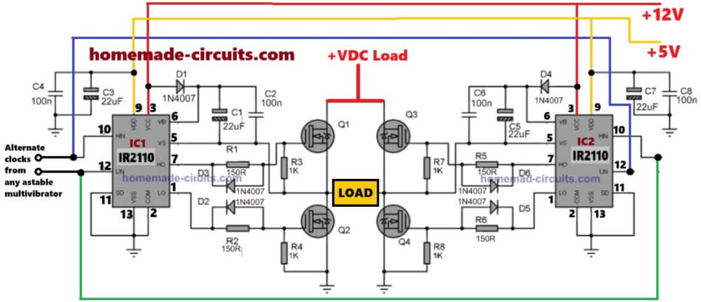
The diagram above shows how to implement an effective full bridge square wave inverter design using a couple of half bridge ICs IR2110.
The ICs are full fledged half bridge drivers equipped with the required bootstrapping capacitor network for driving the high side mosfets, and a dead-time feature to ensure 100% safety for the mosfet conduction.
The ICs work by alternately switching the Q1/Q2 and Q3/Q4 mosfets in tandem, such that at any occasion when Q1 is ON, Q2 and Q3 are completely switched OF and vice versa.
The IC is able to create the above precise switching in response to the timed signals at their HIN and LIN inputs.
These four inputs needs to be triggered to ensure that at any instant HIN1 and LIN2 are switched ON simultaneously while HIN2 and LIN1 are switched OFF, and vice versa. This is done at twice the rate of the inverter output frequency. Meaning if the inverter output is required to be 50Hz, the HIN/LIN inputs should be oscillated at 100Hz rate and so on.
Oscillator Circuit
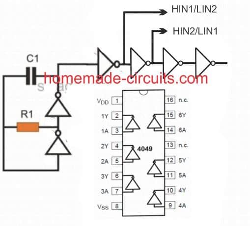
This is an oscillator circuit which is optimized for triggering the HIN/LIN inputs of the above explained full-bridge inverter circuit.
A single 4049 IC is used for generating the required frequency and also for isolating the alternating input feeds for the inverter ICs.
C1 and R1 determine the frequency required for oscillating the half bridge devices and could be calculated using the following formula:
f = 1 /1.2RC
Alternatively, the values could be achieved through some trial and error.
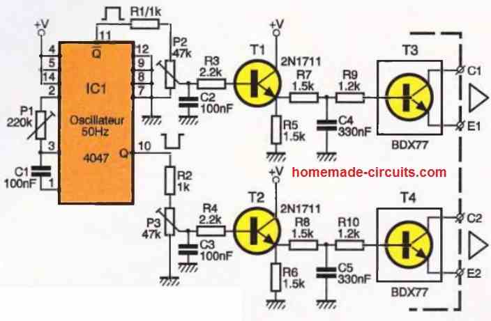
Discrete Full Bridge Inverter using Transistor
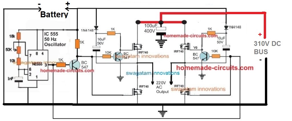
So far we have studied a full bridge inverter topologies using specialized ICs, however the same could be built using discrete parts such transistors and capacitors, and without depending on ICs.
A simple diagram can be seen below:



Questions & Answers
can i use the same schematic for the two half bridge IC but for the MOSFET i will use IRF840 because for my case the VDC=377V, also i will use an external microcontroller for (100KHz-300KHZ)
which schematic are you referring to?
thanks in “Discrete Full Bridge Inverter using Transistor”
BC547❗ change to >360v Bjt : MJE13001 or MJE13003 [very Emportant, not Explode ]
1N4148 Change to >390v Fast Diode such FR107 , UF4006 ,UF4007[for safety ]
two 15v zener needs in parallel with Gate-Source High side MOSFETs
Please remember it is just a basic test circuit setup and modifications can be done as required depending on the application…
Snubber for MOSFETs can be added, that’s fine, and change 1k to 100 ohm or 50 ohm…and change 1N4148 to BA159
hi sir am currently working on class d amplifier using sg3525 ic I couldn’t find any half or full bridge driver ic to be connected to the gates of the output MOSFETs.so I ask can I build a descrete one out of transistors just like the one you describe above?
Hi Abubakar,
yes you can try the BJT based design, however for guaranteed and accurate results, I would strongly recommend the IC IR2110 based full bridge circuit. Let me know if you have any further doubts…
educate me .. u is using an N Mosfet for high side switching
finally after reading all that is required to use P channel and N channel for high side switching , from many data sheets yes you have educated me,
much thanks
regards
Br
Thank you, I am glad it helped you to understand the concepts better…please keep up the good work…
Hie sir, I want to make a 24v Fullbridge inverter , 12 mosfets , 3per channel , can I use transistor level shifters to drive the mosfets instead of drivers?
Hi Majaha,
Basic level shifters will not work for N-channel h-bridge without complex circuitry, so specialized driver ICs will be required, since they can make H-bridge designs very simple and reliable, so driver ICs are recommended.
Some induction furnace designs have the problem that the MOSFET or EGBT burns out quickly and its protection is very weak. I want a design that allows the EGBT to work with the drive.
Hello, I just tried to replicate your circuit in Qspice, but it’s not working. Have you ever simulated it in Qspice or LTspice, or did you just build it directly?
I’ve built a half-bridge with only one driver before, and that worked. Now I’m trying to convert the DC-DC with 30V operating voltage into a DC-AC. Any tips for me?
Hey, the IR2110 circuit is 100% tested and a practically working design.
Make sure the HIN and LIN of the two ICs are correctly swapped….meaning the HIN of one IC joins with the LIN of the other IC and vice versa…
Thank you for your feedback. The HIN and LIN of the two ICs are connected correctly. I can see that the SPWM is correctly inverted in the four inputs. The problem is with the outputs and the voltage at the load. Yesterday, I also sent you an email with the file I created in Qspice. Have you looked at it? Thank you in advance!
Hi, It is not possible for me to troubleshoot a simulator result…however if you build and test it practically and explain me the issue, then I can try troubleshooting it, but not a simulator result…
sorry I did not find any email of your..
pls can you send me a 24v low battery protection circuit diagram for my inverter using sg3524 ic. or using relay to disconnect the supply voltage from entering into the voltage regulator lm7812. with explanation pls
Bright, you can use the following circuit and connect the pin#6 of the opamp with pin#10 of the SG3525:
https://www.homemade-circuits.com/wp-content/uploads/2012/01/Low-voltage-Indicator-1.png
Please replace the 741 with one opamp from IC LM358 and Adjust the preset appropriately to set the cut off point of the Ic.
I power the circuit with 48v battery it blow my high side MOSFET pls what bootstrap capacitor to use because I use 50v/10uf which work on my 24v battery before but now on 48 my MOSFET blow pls help
Your bootstrap capacitor is OK, according to me, even for 48V….
I think you must use snubbers for the MOSFETs, and always use a series bulb initially while testing an confirming a newly built design:
https://www.homemade-circuits.com/explained-snubber-circuit-for-mosfet-h-bridge/
pls what are the things to change if I want to make this ir2110 h-bridge inverter work on a 48v battery. should I change the boost capacitor to what pls.
I made this H-bridge circuit with two ir2110, sg3524 as my oscillator and my battery voltage is 25.6v but when I put my multimeter at the load side of the mosfet for transformer, I was getting 28.0v stable, when I set the preset of sg3524 the voltage comes down to 24.2v to 21.0v and the voltage was fauctuating. pls what do I do. I want to use a transformer from a 24v 2kva inverter.
If your meter is set to read AC, then the voltage looks OK to me, since the AC across the load side will read same as the battery voltage. If the meter is set for DC then you must see around 13V DC on your meter for a 25V battery….
If you want to be 100% sure then you may have to use an oscilloscope to check the waveform across the various points on your inverter.
Right now, you can connect and small transformer across the load side of the MOSFETs and check whether the transformer generates the 220V AC or not…
Nothing needs to be changed except the drain side voltage for the MOSFFETs, except the bootstrap 1uF capacitor voltage, which should be 100V rated. Also consider putting snubbers across each mosfets as explained below:
https://www.homemade-circuits.com/explained-snubber-circuit-for-mosfet-h-bridge/
Pls one of my MOSFET gate resistor of 33kohms spiol can I replace it with 10 ohms resistor in my inverter since it is only one
Why did you use a 33k initially, was there any specific reason? For high frequency operation of a MOSFET through a logic gate, the resistor can be a low value such as 10 ohms. So if your MOSFET gate is connected to some logic IC then yes you can use a 10 ohm series resistor.
pls can I still use 10uf/50,v as boost cap on a 48v to 220v inverter
Yes, because the circuit is still operating with 12V DC only,….the MOSFET side is operating with 48V
pls I want to build 24v inverter h-bridge with ir2110 MOSFET gate driver which value of capacitor to choose as bootstrap capacitor. can I choose 50v/47uf or 50v/10uf
10uF/50V should be quite enough.
El tl494 para que sirve
tl494 is an oscillator IC.
Gracias por ayudarme a mejorar las experiencia en electrónica
Porque los diodos de salida del inversores se calientan
which diodes are you referring to exactly?
hello sir i hope you good,, i have talk with you about full h-bridge solar inverter 5.5kw and volatge from the solar is 490v and i am using SPW47N60C3 mosfet and 10 mosfet on each channel all mosfets i will use 40 mosfets ….10 on each channel i will use 2 IR2110 ic and cd4047 for pwm for 2 IR2110 ic to drive mosfets to make it full h-bridge
i have a question and thanks you for your time.
how much current the circuit need for ics to feed gate mosfets without any problem and what is the best voltage?
Thank you Sayed,
The MOSFET gates are high impedance inputs so the current does not matter, the gates can work with microamperes also, so nothing to worry about the current. The best voltage is 12V.
The ICs might need 5 to 10mA for operating correctly.
pls can any h-bridge pure sine wave 12v inverter transformer work with this circuit
pls if I want to build this inverter to work on a 48v battery, with ir2110 driver can I use a zener/resistor to regulate the 48v from the battery to 12v and 5v to power the ic/ir2110
Yes, you can use zener/resistor for stepping down the 48V to 12V at the VCC pin of the IC…
Yes, any two wire primary/secondary side transformer will work…
okay i want ask you again and i am sorry for taking from you time.sir
i will make circut without transformer to feed the ics and gates of mosfets
12v 150 ma it will handle the gates and ics?
question two the gates takes power from the 2 IR2110 ics and cd4047 right?
No problem Sayed,
Yes 12V 150mA will more than sufficient for the ICs and the MOSFET gates.
Your second question is also correct. However remember that the HIN pin of one IR2110 IC must connect with the LIN pin of the other IR2110 IC, and vice versa.