So this circuit changes 12V DC power from a battery into 115V AC power at 60Hz, 230V 50Hz, depending on the transformer secondary specifications. It can drive small AC electrical items up to 100 watts total power. It uses two UJT transistors to make the 60Hz timing speed and two power SCRs or transistors to drive a center tapped transformer.
Circuit Overview and Main Specifications
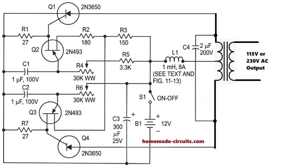
The circuit runs on a 12 volt DC battery. The output gives 115 volts AC at 60Hz frequency and handles 100 watts power. The main parts are two 2N3650 power switches Q1 and Q4, two 2N493 UJT oscillator transistors Q2 and Q3, a 1mH 8A coil L1, and a step up transformer T1.
How the Circuit Works
DC Power Supply and Input Filtering
When switch S1 turns on, 12V DC enters the circuit. Capacitor C3 smooths out voltage variations when heavy switching happens. Inductor L1 blocks sharp high current spikes and keeps battery power clean.
UJT Relaxation Oscillator Stage
Transistors Q2 and Q3 are 2N493 UJTs connected together as an oscillator. Potentiometers R4 and R6 with capacitors C1 and C2 set the switching speed. Adjusting these pots adjusts the circuit to output exactly 60Hz frequency. Q2 and Q3 trigger each other alternately, so one turns on while the other turns off.
High Power Push Pull Switching
The pulses from Q2 and Q3 go to power switches Q1 and Q4. First Q1 turns on and sends current through one side of the transformer primary winding. Next Q1 turns off and Q4 turns on, sending current through the other side of the primary winding. Capacitor C4 helps turn off the SCRs cleanly and stops dangerous voltage spikes.
Step Up Transformer and Output Stage
The alternating current in the transformer primary creates a changing magnetic field inside transformer T1. This high frequency flux generates 115V AC on the secondary output side, ready to power a 100 watt AC load.
Construction and Safety Notes
Power switches Q1 and Q4 will get hot during use, so attach good aluminum heat sinks to them. Coil L1 must be made with thick copper wire because it carries up to 8 amps of battery current. Always take safety steps because the output voltage of 115V AC can give a dangerous shock.
Parts List
| Component Designation | Description / Value |
| Q1, Q4 | 2N3650 High-Power SCRs (or power transistors) |
| Q2, Q3 | 2N493 Unijunction Transistors (UJTs) |
| R1, R7 | 27 ohms resistors |
| R2 | 180 ohms resistor |
| R3 | 150 ohms resistor |
| R4, R6 | 30K ohm Wire-Wound Potentiometers |
| R5 | 3.3K ohms resistor |
| C1, C2 | 1 uF, 100V capacitors |
| C3 | 300 uF, 25V electrolytic capacitor |
| C4 | 2 uF, 200V capacitor |
| L1 | 1 mH, 8A inductor / choke |
| T1 | Center-tapped step-up power transformer (115V AC, 60 Hz, 100W) |
| B1 | 12V DC battery |
| S1 | ON-OFF switch |


Need Help? Please Leave a Comment! We value your input—Kindly keep it relevant to the above topic!