• Skip to main content
  • Skip to primary sidebar

Homemade Circuit Projects

Need circuit help? Post them in the comments! I've answered over 50,000!

Blog | Categories | About | Hire Me | Contact | Calculators-online
You are here: Home / Energy from Magnets and Earth / Make this Gravity LED Lamp Circuit

Make this Gravity LED Lamp Circuit

Last Updated on May 20, 2026 by Swagatam 20 Comments

In this article we investigate a free energy device concept in the form of a gravity LED lamp circuit for illuminating an LED through force of gravity.

Table of Contents
  • The Circuit Concept
    • Not Gravity Rather Human Force
    • Recalling Laws of Thermodynamics
    • Circuit Diagram Layout Details
    • How the Mechanism Works
    • The Role of SW1 Switch
      • Wheel Handle Alternatives

The Circuit Concept

Gravitational force is an awesome source of energy, amply available on this planet, and easily accessible, however, nobody yet has been able to convert this force into radiant energy (perpetual), simply because that's impossible.

In this post we'll learn a simple manipulative technique which allows a user to channelize gravitational force into a work force which can be used for illuminating an LED lamp and for charging a battery. The idea was suggested by Mr. Pritam Bhowmik.

Recently, the idea of using gravitational force for illuminating an LED has gained a huge amount of popularity, and quite a few companies can be seen encashing on this by selling equipment designed for generating electricity just by hanging a load and allowing gravity to do all the hard work, the result being pure free electricity.....looks too good isn't it, but everything that appears to be too good = = FAKE.

Not Gravity Rather Human Force

Having said that, the idea definitely has the potentials of providing electricity however the "name" of the design needs to be changed to "Human Force free LED lamp" instead of gravity lamp, because although the gravity would be doing all the work of keeping the suspended load under pressure for implementing the intended results, for hoisting the load back to top repeatedly would require human energy which is by no means free, .....yet still with little thinking and a smart innovation the whole concept of making a gravity lamp circuit can be made feasible. The following discussion will make it clearer.

Recalling Laws of Thermodynamics

Basically, it's the first law of Thermodynamics that restricts the possibility of any perpetual or "radiant energy" concept to become successful, according to this law a particular form of energy can only be transformed to another form of energy, but energy can never be created.

No matter how strict the above law my be, it never stops anybody from making efficient machines or enhanced machines for achieving highly efficient conversion of energy from one form to the other desired form.

A couple of such manipulated overunity concepts (developed by me) can be studied in the following links:

Free energy from pendulum

Running motorcycle on water

Returning to the proposed gravity LED lamp circuit, the idea can be implemented by employing the following simple set up.

Circuit Diagram Layout Details
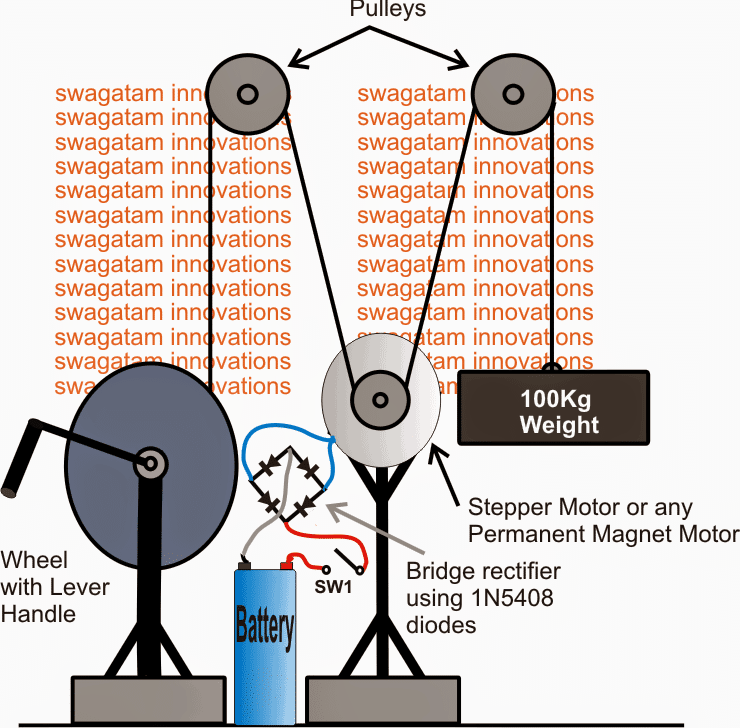
The idea looks pretty simple, in the set up image above we can see two pulleys (enhanced with ball bearing) on the top, and a generator motor at the bottom center.

We can also see a relatively large wheel with a lever handle mechanism on the left hand side of the set up, while on the right side a suspended heavy load.

All the above mechanisms are linked up with a rope, such that the mechanism becomes operational as I have explained below:

How the Mechanism Works

The idea here is to rotate the wheel handle with manual force in order to pull the heavy load upwards until it reaches the maximum height achievable, then release the wheel so that the load can now fall down freely due to the action of gravitational force.

While this happens the motor being a part of the pulley system also gets rotated and begins generating effective electricity for either charging an attached battery or illuminating an LED.

The switch SW1 plays an important role in the whole system, this switch should be in the OFF position while hoisting the load upwards, and in ON position before the wheel handle is about to be set free by the user.

The Role of SW1 Switch

This is important because with SW1 in switched OFF position the motor spindle acts like an ordinary freely moving easy to rotate pulley, and offers minimal resistance to the person hoisting the load, and as soon as SW1 is closed the motor gets loaded, and offers much higher resistance while moving.

Thus the suspended load now gets influenced by the loaded motor and instead of falling down freely moves relatively at a slower pace towards the ground and the gravitational has do apply an equivalent amount of work force for generating electricity from the motor.

This is obviously just an example which shows how a relatively lower input force can be used for achieving much higher levels of output power, through a very ordinary and easy to implement mechanism.

Wheel Handle Alternatives

The wheel handle mechanism can be replaced with other forms of mechanisms that may be capable of producing even higher efficiency for the same. Some of the examples are a 4 pulley/chain mechanism, screw jack mechanism etc.

The load on the motor should be optimally calculated so that the gravity load comes down at a much slower pace, or the height of the upper pulleys may be extended to higher points for inducing a sluggish unwinding procedure by the load.

The motor for this gravity LEd lamp circuit could be an ordinary permanent magnet motor, a stepper motor or geared type of electromagnet motor.
You'll also like:

  • 12V batteryMaking a Self-Powered Generator
  • TEGMaking a Thermoelectric Generator (TEG) Circuit
  • freeenergybicyclegeneratorBicycle Generator Circuit
  • freewheel 2Generate Electricity from Regenerative Braking System for Vehicles

Filed Under: Energy from Magnets and Earth Tagged With: Gravity, Lamp, LED

About Swagatam

I am an electronics engineer and doing practical hands-on work from more than 15 years now. Building real circuits, testing them and also making PCB layouts by myself. I really love doing all these things like inventing something new, designing electronics and also helping other people like hobby guys who want to make their own cool circuits at home.

And that is the main reason why I started this website homemade-circuits.com, to share different types of circuit ideas..

If you are having any kind of doubt or question related to circuits then just write down your question in the comment box below, I am like always checking, so I guarantee I will reply you for sure!

Previous Post: « 1 watt LED Lamp Circuit Diagram using SMD LEDs
Next Post: Cellphone Charger Circuit Using Pendulum Generator »

Have a question or feedback? Feel free to ask below—just make sure it relates to the post above!

Subscribe
Notify of
guest
guest
20 Comments

Primary Sidebar

My YouTube Channel

Circuit Simulator: Draw and Simulate Schematics

circuit simulator image

Categories

  • Arduino Projects (95)
  • Audio and Amplifier Projects (134)
  • Automation Projects (18)
  • Automobile Electronics (104)
  • Battery Charger Circuits (90)
  • Datasheets and Components (109)
  • Electronics Theory (151)
  • Energy from Magnets and Earth (43)
  • Games and Sports Projects (11)
  • Grid and 3-Phase (20)
  • Health related Projects (27)
  • Home Electrical Circuits (13)
  • Indicator Circuits (16)
  • Inverter Circuits (98)
  • Lamps and Lights (161)
  • Meters and Testers (72)
  • Mini Projects (28)
  • Motor Controller (68)
  • Oscillator Circuits (30)
  • Pets and Pests (15)
  • Power Supply Circuits (91)
  • Remote Control Circuits (50)
  • Security and Alarm (65)
  • Sensors and Detectors (107)
  • SMPS and Converters (46)
  • Solar Controller Circuits (62)
  • Temperature Controllers (44)
  • Timer and Delay Relay (51)
  • Voltage Control and Protection (44)
  • Water Controller (37)
  • Wireless Circuits (31)

Subscribe to get New Circuits in your Email

Other Links

  • Privacy Policy
  • Cookie Policy
  • Disclaimer
  • Copyright
  • Videos
  • Sitemap

People also Search

555 Circuits | 741 Circuits | LM324 Circuits | LM338 Circuits | 4017 Circuits | Ultrasonic Projects | SMPS Projects | Christmas Projects | MOSFETs | Radio Circuits | Laser Circuits | PIR Projects |

Recent Comments

  • Swagatam on High Voltage Meter Circuit [for Measuring 10kV]
  • Swagatam on About Me
  • chukwuamaka on About Me
  • Brian Harding on High Voltage Meter Circuit [for Measuring 10kV]
  • Swagatam on Police/Ambulance Siren Circuit with Rotating Beacon Light

Social Profiles

  • Twitter
  • YouTube
  • Instagram
  • Pinterest
  • My Facebook-Page
  • Stack Exchange
  • Linkedin

Calculators

  • ZVS Induction Heater + Tank Calculator Tool
  • Zener Diode Calculator
  • Wire Current and Thickness Calculator (Ampacity Calculator)
  • Voltage Divider Calculator
  • Transistor Base Resistor Calculator
  • Transistor Astable Multivibrator Calculator
  • TL431 Calculator
  • Solar Panel, Inverter, Battery Calculator
  • Ferrite Core Air Gap Calculator Tool
  • Parallel MOSFET Calculator Tool: How to Connect MOSFETs in Parallel Safely
  • LC Resonance Calculator for EV Battery Charger Circuits
  • LED String Series Resistor Calculator
  • PFC (Power Factor Correction) Calculator Tool: 3kW
  • Passive Power Factor Correction (PFC) Calculator
  • LM567 IC Calculator Tool
  • SMPS Flyback Boost Converter Calculator
  • Shunt Resistor Calculator for Ammeters
  • SCR and Triac Gate Resistor Calculator
  • Battery Back up Time Calculator
  • Boost Converter Calculator (Non-Isolated)
  • Bootstrap Capacitor Calculator
  • Buck Converter Calculator
  • Buck-Boost Converter Calculator
  • Capacitance Reactance Calculator
  • DCM Flyback Transformer & Wire Gauge Wire Size Calculator Tool
  • Filter Capacitor Calculator
  • IC 4047 Calculator (Frequency and PWM)
  • IC 4060 Calculator
  • IC 555 Astable Calculator
  • IC 555 Monostable Calculator
  • IC SG3525, SG3524 Calculator
  • Inductance Calculator
  • Induction Heater Inductor and Resonant Frequency Calculator
  • Induction Heater Work Coil Calculator
  • Inverter LC Filter Calculator
  • LC Resonance Calculator
  • LED Current Calculator
  • LM317, LM338, LM396 Calculator
  • NAND/NOT Gate RC Values Calculator
  • NOT, NAND Gate Frequency Calculator
  • Notch Filter Calculator Tool
  • Ohm’s Law Calculator
  • Phase Angle Phase Shift Calculator
  • Power Factor (PF) Calculator
  • RC Filter Calculator
  • Reactance Calculator
  • Sine Table Calculator for SPWM Arduino Code
  • Small Signal Transistor(BJT) and Diode Quick Datasheet
  • SMPS Calculator for Toroidal Ferrite Transformers
  • SMPS Flyback Transformer Calculator – Design by Target Duty Cycle
  • TL431 Calculator
  • Op-Amp Hysteresis Resistor Calculator

© 2026 · Swagatam Innovations