In this post we'll try to investigate the making of HHO gas in automobiles for enhancing their mileage by approximately 50% or more, that means a reduction of petrol or diesel consumption by the same amount.
In the previous post I tried to put forth an innovative design of a high voltage low current generator which could be used for splitting water into HHO gas (by decomposing the H2O bond into two parts of hydrogen and one part of oxygen).
Using a high voltage for the electrolysis allows the breaking apart of the water molecules by brute force without the need of a higher magnitudes of current (amps), which in turn makes the procedure extremely efficient.
We can understand the above logic by analyzing the following example:
Higher Voltage is more Effective
Suppose we have a 12V battery capable of delivering a maximum current of 7.5 amps, if we use this battery power for the electrolysis we would probably be implementing it very inefficiently and the power required for the electrolysis would easily exceed by far than the power of the accumulated HHO gas in terms of megajoules.
However if the same 12V/7AH is boosted to say around 20,000 voltage with a current as low as 5mA would be able to yield better results (many people might not agree with this).
Moreover since this high voltage is pulsed using a PWM circuit, the sharp rise and fall of the pulses adds up to the efficiency level of the process.
Many critics argue and don't substantiate the use of a high voltage for yielding higher efficiency, however the following few examples provide us sufficient logical evidence regarding why a high voltage could be more effective than using high current for the electrolysis of water.
Passing a low voltage, high current potential through a very high resistance could be useless because the current would be restricted by the high resistance and produce little effect on the process. Since pure water can be notorious with its resistance value (pure water may have a resistance as high as 200k or even more), a high current at low voltage would be quite ineffective.
On the contrary a higher voltage would be strong enough to tear apart the water high resistance and be comparatively more effective, even though a lot lesser number of electrons would be passing through, but nevertheless we would see electrons crossing over with better efficiency.
Assessing with Practical Examples
Just try applying a 12V/100amp through a 200k resistor and check the current with an ammeter, according to Ohms law it would be around I = 12/200000 = 0.00006amps or 0.06 mA, in contrast if a 20,000 volt is used we would find it to be capable of delivering I = 20000/200000 = 0.1 amps or 100mA, that looks much impressive, although we wouldn't want 100mA to be used for electrolysis in order to avoid explosions or atomization of water, we can expect about 10mA to be quite sufficient for the process.
Another example that looks quite relevant to the subject is our body itself, we experience a lethal shock when we come across a high voltage AC with any part of our body, but in contrast if we touch a lower potential input such as a 12V AC we might not feel anything regardless of how high the source may be rated with amperage.
The above example provides an authoritative proof regarding the power of high voltage in terms of its riping ability through high resistance passages, the same may be true with lightning thunder bolts which are equipped with millions of volts and that's why are able to knock out the huge atmospheric barrier and reach the earth surface.
Having said this, in the proposed use of HHO gas in automobiles one must be careful regarding not supplying the high voltage with high current, otherwise that might lead to an explosion inside the water and result in atomization of water molecules which is definitely not an electrolysis.
Installing HHO Fuel Cell in Automobiles for Enhancing its fuel Efficiency
Here we'll talk about using the HHO fuel cell idea in a motorbike and learn the procedure of installing and integrating it with a motorcycle engine.
In one of our previous posts I have explained how HHO gas could be produced using a high voltage CDI coil circuit, we will use the same design for the proposed implementation and for enhancing a motorcycle's fuel efficiency.
Since your motor cycle would be already having a CDI ignition system this could make things much easier for us, since we could simply borrow it's function for the discussed purpose.
However we must be careful about a couple of things: the sharing of the high voltage pulse from the existing CDI should not hamper the actual ignition of the bike for which the CDI coil is originally installed.
Secondly, we don't want the vehicle's alternator to work extra hard for compensating the sharing of the CDI sparks with our HHO fuel cell.
Using Spark Suppressor
The above situations can be countered by employing a spark arrestor resistor or a spark suppressor device. This device is normally used in series with the high tension input from the CDI before it enters the spark plug.
As the name suggests the spark suppressor is used for suppressing excessive voltage from reaching the spark plug thus helping to cancel out the generation of unnecessary RF disturbance and noise.
This means that in normal conditions the spark plug would be wasting a good amount of energy by shorting the high voltage across it's spark gap which apparently looks pretty small compared to the enormous voltage it's been fed.
The use of a suppressor ensures that the excess voltage which would otherwise become wasted in the spark plug now gets restricted and is converted to heat, which is again a wasted energy unless it's diverted for some useful purpose.
The utilization of a spark suppressor resistor and by diverting the excess energy from the CDI coil to the HHO cell appears to be a smart move.
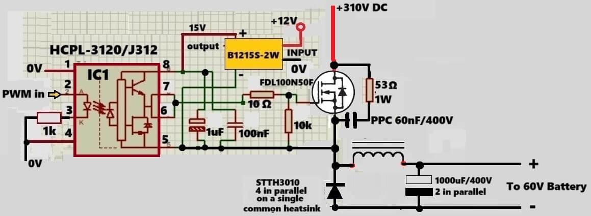
Circuit Diagram
WARNING: THE DESIGN EXPLAINED BELOW INVOLVES EXTREME HIGH VOLTAGES WHICH CAN BE LETHAL IF TOUCHED IN AN UNCOVERED CONDITION. EXTREME CAUTION IS ADVISED WHILE CHECKING OR HANDLING THIS EQUIPMENT. HHO GAS IS DANGEROUS, AND CAN LEAD TO EXPLOSIONS, AGAIN EXTREME CAUTION IS ADVISED WHILE GENERATING THIS GAS. THE AUTHOR CANNOT BE HELD RESPONSIBLE FOR ANY ACCIDENTS WHATSOEVER DUE TO NEGLIGENCE OF THE USER.
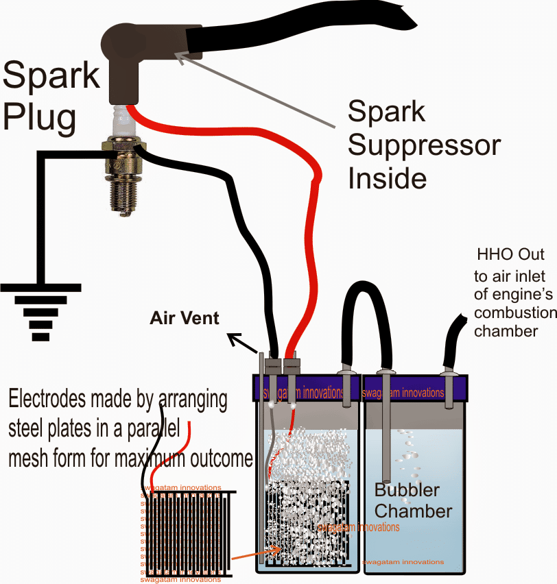
An easy to understand set up for generating "on demand HHO gas" can be witnessed in the above diagram.
The electrodes are made out of good quality stainless steel pates which are appropriately arranged in a mesh like formation through a face to face intersection but without touching each other.
Using Baking Soda to Increase Efficiency
A little baking soda is added in the water for speeding up the electrolysis process and assisting the electrons to flow with greater efficiency.
In the left container we can see an air vent pipe, this is introduced to allow air to pass inside the vessel as the water is electrolyzed into HHO gas. This air vent pipe prevents vacuum formation in the vessel while the electrolysis is in process.
Since the input high voltage is derived from the motorcycle's CDI coil or the spark plug, we can assume it to be in sync with the engines RPM and in accordance with the speed of the vehicle. Therefore the chance of inducing a disproportionate amount of HHO inside the combustion chamber is automatically controlled, making the procedures much safer and healthier for the vehicle's engine.
The HHO gas output from the bubbler chamber is directly integrated with the air intake passage of the motorcycle's combustion chamber.
Once the above set up is installed and initiated, an immediate improvement in the performance of the motorcycle's engine could be expected and a drastic reduction in the consumption of the primary fuel could be witnessed.
WARNING: THE PROPOSED CONSTRUCTION GUIDE OF HHO GAS IN MOTORCYCLE FOR IMPROVING ITS EFFICIENCY HAS NOT YET BEEN TESTED BY THE AUTHOR PRACTICALLY, EXTREME CAUTION AND CARE MUST BE EXERCISED WHILE TRYING THE EXPLAINED THEORY. THE AUTHOR CANNOT BE HELD RESPONSIBLE IN AN EVENT OF AN ACCIDENT OR A FAILURE OF THE PROJECT WHILE CARRYING OUT THE EXPERIMENT.


Questions & Answers
Oh good grief.
1) You are not ‘creating’ energy, you are converting energy. HHO ‘gas’ does not exist. Look at the spout when you next boil water: you can’t see the vaporised water just about the spout: it must condense before it becomes visible. When you electrolyse water, you get O2 at one electrode and H2 at the other. These two mix to form an explosive gas with a very low ignition energy: 2mJ will do. In the proposal, these are inside a sealed container, so if they do explode then the outcome will likely be complete destruction of your kit.
2) Burning gasoline released about 47MJ per kg. Combustion inside your engine is about 98% efficient: this is required to meet emissions standards as the controlled emissions are either incomplete combustion (HC & NMOG) or excess combustion (NOx).
3) There is no grand conspiracy of OEMs or ‘big oil’ working to undermine the efficiency of your engine/vehicle. I work for an OEM. Every few years I get an unsolicited proposal that, in a physics defying way, will significantly improve the gas mileage. I’ve tested a few on engine dyno (the gold standard of efficiency testing) and NONE of them worked: not the magnets around the fuel line; not the alloy of antimony and tin pellets in the fuel tank; not the vortex exhaust, or a vortex in-front of the MAF.
4) Commercial electrolysers already exist to create small quantities of Hydrogen. However, your problems will start there: in what are you going to store your Hydrogen? Hydrogen vehicles use a tank pressure of 70MPascals (cars) or 35MPascals (commercial vehicles). Note that you as a human have no detection mechanism for a hydrogen leak: it has no smell, and burns with a colourless flame. The first you know that a) you have a leak and b) it’s on fire, will be when your clothes/hair/vehicle start burning. Don’t Jerry-Rig this: you are literally playing with fire. Swagatam can confirm email is at an OEM.
Hello my Friend, hope you are well!
Quick question for you, if I’m trying to put a capacitor across the output of my HHO cell to smooth out the current, what size capacitor/supercapacitor do I need?
My cell is powered by a 12v car battery and the battery is being charged by a 12v 30a charger connected to 220v outlet at home.
Hi eq,
the capacitor can be any large value capacitor, the bigger the better, like a 2200uF, or 4700uF, or even a 6800uF etc.
thank you!
first of all I just want to say ‘Thanks’.
you answered some questions for me like 5 YEARS ago.
HHO question for you, slightly off topic*
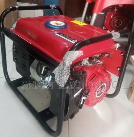
I’m following an online plan to build a simple 12v Hho cell but it requires 20a. I can’t get 20a since it’s a 6.5 Chinese generator and doesn’t have a battery as you know(& charging coil only makes like 3a I think)
how can I over come this on a small budget?
the idea I have is too get a 20a-30a 12v battery charger and run the cell from this from the output side of the generator, is this even possible?
please let me know what you think, thanks!
You are most welcome eq!
using 12V 20 amps to generate HHO gas means involving 20 * 12 = 240 watts of power. In that case the generated HHo gas should be able to power a motor rated to handle more than 300 watts, only then it will be a beneficial deal, otherwise it will be a waste of energy and efforts, right? or maybe I did not understand your requirement correctly…please let me know.
yes, correct, it’s just a basic 1500Watt generator.
so if I understand you correctly, you are saying about 240 watts will go towards powering the HHO and the rest of 1260 will be available to power other devices?
so in your opinion is it worth it or is this better on a large generator?(if so what size generator do you recommend?)
do you also recommend this approach(using the generator output to power the cell) or would you do it differently if it was you?
Sorry, I don’t think I understood your application correctly.
Can you please explain the flow diagram or the flowchart… what is the purpose of the HHO gas here.
You said it was a 6.5 Chinese generator, then what is this basic 1500Watt generator?
hello, sorry for the misunderstanding.
What I was trying to say is that it’s a 1500watt generator and like you mentioned it needs about 240 watts to power the hho. so I’m left with about 1260 watts to power other devices.
What I’m trying to understand is how to efficiently power the hho cell because the generator DOESN’T HAVE BATTERY where I can connect the hho cell, so I have to use a different source(the idea I have is to connect the hho once the generator is running: connect it to the 220v outlet and the use a 20a 12v battery charger to run the hho cell)
So I am interested in your opinion, whether this is the best method to power the hho cell(if not, what would you recommend)?
What is the voltage output from the generator? If you want extreme efficiency then you can consider converting the generator output to a 3V DC, using a buck converter, and then use this DC for the electrolysis of water with a drop of H2SO4 in it, to generate high amounts of HHO with high efficiency.
im new to all this, can you please clarify
so based on the instructions for the cell to work efficiently it says:
I need 12v. 20a
the device has 6 cells
which is about 2v per cell(you need 1.24v per cell for maximum efficiency)
so will the 3v buck converter be enough since I require about 12v total?
what is the reason for the buck converter?
my generator is 1500watts
and has 220v outlet
Sure, let me check, I will try to design it soon and let you know!
thanks for all your assistance Sir!
you are welcome eq…
wow I just saw the circuit you designed for me.
Thank you Sir, you’ve true gone Above and Beyond, can’t thank you enough.
I’ll find someone who understands circuits to look over it for me!
While on the subject of circuits, what do you think of this one

this one is simple enough for even me to understand it without any elect engineering background.
my question for you is, if this was done with two 72v batteries, what can you use as the one way diode?
You are most welcome eq, for the diode in the attached diagram, the diode will depend on the switching current and frequency. If the current is say 5 amps, and switching frequency above 1kHz then you can use any fast recovery diode rated at 5 amp, and so on. If the frequency is lower, then the diode can be any rectifier diode like 6A4…
sounds great, thank you!
Ok, here’s the circuit you can build for getting 12V from 220V for your HHO cell. Make sure to use appropriately dimensioned super enameled litz wire for the inductor, wound over a ferrite ring core.
Actually I was referring to 3V per cell, but no issues, 2V is even better, so yes 12V 20 amp is good enough for your 6 series cells application.
Let me know about the input voltage specifications from the generator, then I may try to figure out the buck converter design…
this is the hho cell I’m trying to use
https://www.homemade-circuits.com/wp-content/uploads/2025/06/HHO-pdf.pdf
(as you can see it requires 12v 20a to be most efficient without getting hot)
this is the type of generator I have
OK, thanks, Got it!!
Hello, your original design for this topic is removed by you for security reasons, but topic is the same, question is in order to produce hho with HV in pure water, by dumping HV in KV but amps must be restricted in miliamps, exactly below 100ma?
Hi, thanks for your suggestions…Yes, the current will be low and much below 100mA for the above project…
I’m more interested in you original cdi circuit, and several other projects, one of them is Meyer brushed rewinded alternator… To keep it short, plan is to build-replace alternator stator windings with 4x CDI coils around rotor to simulate 4x phases with HV impulse.. For now
i know Meyer dereulated multi phases alternator work but not enough gas to start engine like him, he probably rewinded stator to 9 phases with thin vire to get HV, Cdi would be simpler to build and achieve same thing.
The basic CDI circuit can be found in the following links:
https://www.homemade-circuits.com/how-to-make-capacitive-discharge/
https://www.homemade-circuits.com/make-this-enhanced-capacitive-discharge/
I have not yet studied the Meyer alternator, so unable to provide my opinion on this.
I hope you succeed with this project.
Please do keep us updated with the results.
Additionally; I recommend you to examine the “Voltage Multiplier” circuits with only diodes and capacitors from 220Vac. It will be easier and more practical to obtain High voltage DC by adding it to the output.
Stay happy.
Şafak TAŞKIN from TURKEY.
Thank you for your interesting feedback. yes, that’s definitely worth trying.
I appreciate the idea.
Greetings. It was a project I did about 20-25 years ago. Regarding high voltage, I definitely agree with you, as is my experience. Best Regards.
Safak TASKIN from TURKEY.
Good morning sir, How are you doing today sir, sorry to disturb you again sir, Sir I construct hho cell using aluminium pipe with each having a distance of at least 1mm apart, is the distance apart OK?, another thing the amount of heat been dissipated is a lot sir
Hi Tunji,
what DC voltage are you using, and are you using any chemical in the water? If the DC is 3V and above and there is no chemical used, then 1 mm distance is fine.
If you are using a chemical like sulphuric acid, or similar then you can try wider distances also.
Hi sir, please I need your advice on this Dc generator, I need to know if I can use it for the experiment above, and what should be the distance apart for the Aluminum rod that I’m using
https://www.konga.com/product/switching-power-supply-ac-dc-power-supply-5v-40a-200w-6079466
Or Aliexpress
https://www.aliexpress.com/i/2251832698536301.html?gatewayAdapt=4itemAdapt
Or which power supply can you recommend, and also if 12v 1A transformer to Dc, can be made somehow efficient
Hi Tunji,
Yes, you can use those power supplies for generating HHO gas.
Alternatively you can simply use a 12V 1 amp AC to DC power supply for generating HHO gas.
For 5V DC, the distance between the electrodes inside water can be around 1 inch.
For 12V it could be anywhere between 2 inches and 1 inches.
The closer the better.
The cross section area of the electrodes also matters, bigger cross section will produce higher amounts of HHO.
I’m using 220V Dc, converted directly from AC, I’m not using any electrolyte.
In that case you can keep 2 inches distance between the probes.
Please remember that using 220V can be fatal if not handled carefully and with necessary precautions.
You are doing it at your own risk.
OK, thank you so much sir, I really appreciate it.
You are welcome Tunji…
Hi, I saw a video on YouTube, where someone is using Dc to Dc boost converter for Hho gas generator, with potassium hydroxide or sodium hydroxide in the water.
Sir with this type of implemention will the hho gas be efficient? If what modification can be done to increase it production?
Boost converter will work if it has high current otherwise it won’t be efficient.
You can try something like this:
https://www.homemade-circuits.com/how-to-generate-pure-oxygen-and/
Wow, thank you so much sir for that quick reply, though I still have one more question sir, can I 3v to 6v ==> 10kv to 20kv power module, will it work?, is it effective? Or just a waste power? And which is preferable Sodium hydroxide or Potassium hydroxide as a solvent in water?
Thank you Tunji, If you are using a catalyst then you just need 3v for efficient generation of hho, rest everything is waste of power.
A drop of sulphuric acid is actually the best catalyst for fast electrolysis of water, however out of those two, sodium hydroxide is the preferable one.
if im already using KOH on my drycell hho setup, does adding sulfuric acid make it more efficient?
my system draw around 3.4a @ 12v
If you are already using KOH in a dry cell HHO setup then adding sulfuric acid will not make it more efficient, because KOH is alkaline and sulfuric acid is acidic…. so when both mix they neutralize each other and form potassium sulfate and water, now this reduces OH− ions which are actually needed for proper electrolysis. So heat increases, gas output becomes unstable, and also efficiency goes down instead of up, hence a dry cell must be either alkaline with KOH or acidic, but never both mixed together.
Sorry, to disturb you again sir, I wanted to use multiple 3.7v lithium batteries, how should I connect them in series or in parallel for efficient Hho generation, thank you sir.
You can connect them in parallel.
Thank you so much sir
You are welcome Tunji…
OK thank you so much sir
So spark plug is for gating?
Couldn’t you do the same with just a coil pack? Some go from 20000v to up to 50000v. I know I am making a full inclosed system with that.