This pendulum electricity generator can be used in villages for charging cellphones free of cost just by applying momentary pushes to the pendulum frequently or as desired throughout the day.
Pendulum as Free Electricity Generator
In one of my previous articles I explained about the high efficiency value of a pendulum mechanism, and how it could be used for generating almost free electricity using a minimal input effort, in this article we'll learn how the same principle can be executed for charging cellphones free of cost.The following figure shows the basic set up which can be applied for charging cellphones free of cost.
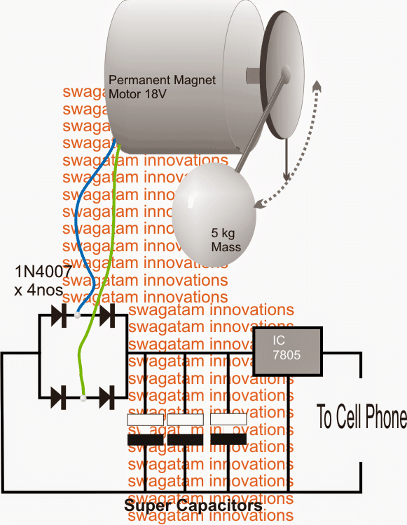
Referring to the figure above, we can see a relatively simple set up consisting of a DC motor rated at 12V, 5amp (or any other specs depending upon the output requirement), a bridge rectifier, a few super capacitors and a 7805 IC voltage regulator.
Circuit Operation
The motor spindle is appropriately configured with a mechanical pendulum assembly consisting of a pulley and a shaft, the shaft has a heavy spherical mass attached with its lower end.
The whole system is appropriately clamped over a firm base using brackets and angles (not shown in the image)
The functioning of the proposed free pendulum cellphone charger is rather simple.
The spherical mass is kept oscillating by applying frequent flicks manually, which is repeated only while the pendulum system is about to come to a halt.
Being extremely efficient by its nature of functioning, the pendulum can be expected to oscillate for quite sometime with every push, generating precious electricity for the connected cellphones, charging them almost free of cost.
The super capacitors are added for ensuring maximum outcome, however any ordinary high value capacitor may also be used with effective results, such a a few 2200uF/25V would be just enough.
In order to achieve maximum efficiency and higher sustain rate of the mass, two things needs to be taken care of: 1) the weight of the attached mass and 2) the length of the pendulum shaft, both of these are directly proportional to the efficiency of the system.
Meaning if the mass is more heavy and/or the shaft is lengthier would result in greater efficiency from the system, ensuring lesser manual effort for keeping the oscillations sustained for longer periods.
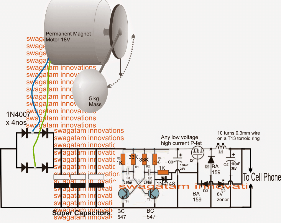
Using IC 7805 Regulator
The IC7805 is a linear voltage regulator IC which implies that it would dissipate heat significantly during the charging procedure which in turn might result in a reduced efficiency.
In order to overcome this, one may consider employing a buck converter circuit at the output instead of the shown 7805 IC, as shown in the following image
Circuit Diagram


Questions & Answers
Swag,
Same idea, different config! Pendulum/Lever, Two-stage Mechanical Oscillator.
Looking for a STEP MOTOR:
1). Plunge force
2). Pendulum weight
3). Low RPM
Glad to share image of model to verify.
Thanks
Please reply!
Thanks Kevin, if possible I will surely try to design the concepts specified by you, and post them here!
Kevin Asks?
STEP MOTOR for? TARGET—OUTPUT—5.0V—2A? (BALLPARK)
PURPOSE: TO—CELL—PHONE
🙂
You are a very capable person!
Hi sir, if I have connected 18 Pcs of 1watt LEDs(18watts) in parallel, so can I power them using 5v 1 amp input (5w).?
Iam very interest about the circuit,thanks for sharing,
but i have no knowledge of electronic,
my questions is,,,
How long the pendulum and keep self moving?…and for firts time to make it running, do we need to give external force?like move the pendulum with our hand?
You can connect them, but the light will be very dim…
I have checked practically the light is very good. One more question please, what is the maximum voltage 1w led can bear safely.
if you compare it with the actual light, you will find it to be low….
3.3V is the correct (optimal) operating voltage for a 1 watt 350mA LED
My input current is 1A, and the old USB emergency lamp which I made 6 months ago also working very nicely till now, (very perfect even with having 5v ni-cd battery pack).
My current input for 18 LEDs in series is 1A,.
With 3.3v the brightness is less,..
Is there any circuit with you for voltage doubler or enhancer which can make 6v input to 7 volts or 8volts.(transistor and mosfets operated circuit, no ic.)
3.3V is the right voltage for any white LED, and 1amp for 18nos 1 watt LED is too less, so I cannot discuss anything related to this topic since it is being done with wrong specifications.
OK, you said your 18 LEDs are in series, in that case the voltage should be 3.3 x 18 = 59V, and the current should be 300mA.
so make sure you apply this much power to your LEDs…
With 3.3v it’s not enough light but I’m powering them with 4.7 to 5v @1Amp and it’s performance is good, is it good?
It is wrong. The right specs are 3.3 V 350 mA, or 300mA is better, but since since your input current is low, 5V might work, check the voltage across the LED, if it is dropping to 3.5V, then it is OK, if not them it will damage your LEDs very soon
Sir what type of motor in the circuit above?
any DC brushed motor will do….
Cpu fan how to make wind mobile charger?
CPU fan is too small to generate sufficient current for charging a cell phone.
Can i use a dc geared motor as the generator? I want to use as a free energy generator to charge battery. Which should i buy? Also mention its price
No, a geared motor is not recommended here. you can try a 9V/2amp BLDC motor, I am not sure about the price…