In this post I have explained a simple yet very useful 0 to 50V dual power supply circuit which will enable a full 0 to maximum dual voltage +/- control of the input power supply DC. It also includes a wide range current control feature right from 0 to 10 amps. The idea was requested by Mr. Tamam.
Technical Specifications
It was my long term dream to build a 2 channel power supply for personal use, I have seen a lot of circuits, but those does not fit my criteria.
However, please take a look at the following requirements and let me know if its possible or not, if possible I will be the happiest person in the world.
1. Output voltage range: -50V to 0V to +50V ( must be adjustable by individual channel )
2. Output Current range: 0A to 10A ( must be adjustable by individual channel )
3. Output would be Duel channel, means total 6 outputs,
Channel 1 (Positive, GND, Negative) Channel 2 (Positive, GND, Negative)
4. Power Supply Unit should contains 2 Voltmeters and 2 Ammeters (Analogue) for 2 individual channel.
5. Power Supply Unit must have short circuit protection and cooling fan featured and extreme heat protection.
6. I don't want to use any PIC or AVR, so please avoid those.
Money is not a matter here, I will spend continuously until above requirement meets.
Even If I need any custom transformer I will order and make it from our local area.
I have seen many ready made power supply in market but I want to make it by own hand. You just show me the way... please bro, I will be pleased to you for lifetime.
Thank you very much !!
Best Regards,
Tamam
For calculating the part values accurately, you can refer to this bench power supply article
Circuit Diagram
The Design
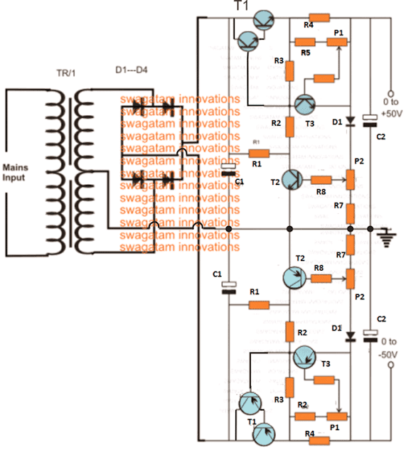
The basic design of the proposed 0 to 50V variable dual power supply circuit with 0 to 10 amp variable current facility is shown in the above figure.
The entire design is transistor (BJT) based and is virtually indestructible. Moreover it's equipped with an over load and over current protection features.
The two section included in the design are exactly similar with their configurations, the only difference being the use of PNP devices in the lower configuration while NPN in the upper configuration.
The upper NPN design is configured to produce a variable response right from 0.6V to 50V positive while the lower PNP section becomes responsible of producing an oppositely identical response from -0.6V to -50V output.
The Transformer Specs
The maximum limit could be suitably changed simply by changing the voltage rating of the transformer. However for higher voltages you may have to appropriately upgrade the BJT voltage ratings accordingly.
In both the designs, P2 executes the function of varying the voltage levels as desired by the user, while P1 functions as the current regulator and is used for adjusting or setting the output anywhere from 0 to 10 amp current. Here too the maximum rating depends on the selection of the transformer amp rating and may be changed as per individual preferences.
T1s in the both the sections become the fundamental part or the heart of the entire voltage control functioning in the circuit, which becomes possible due to the popular common collector configuration of the devices.
The other two active BJTs only help to implement the same just by controlling the base power of the T1s thus making it possible to adjust the thresholds to any desired user defined voltage and current levels, as per the ratings of the transformer or the input supply.
You may also like this LM317 based Dual Power Supply Circuit
Parts list
- R1 = 1K, 5 watt wire wound
- R2 = 120 Ohms,
- R3 = 330 Ohms,
- R4 = to be calculated using Ohms law, R = 0.6/Maximum Current Limit, Wattage = 0.6 x Maximum Current Limit
- R5 = 1K5,
- R6 = 5K6,
- R7 = 56 Ohms,
- R8 = 2K2,
- P1,P2 = 2k5 presets
- T1 = 2N6284 + BD139(NPN), 2N6286 + BD140(PNP)
- T2, T3 = BC546 (NPN) BC556B (PNP)
- D1, D2, D3, D4 = 6A4,
- D5 = 1N4007,C1, C2 = 10000uF/100V,
- Tr1 = 0 – 40 Volts, 10 Amp
Using Op Amps and TIP35
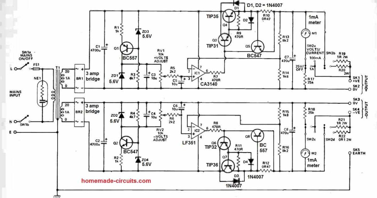
Here's another accurate adjustable dual power supply circuit, for your reference:
Using MJ2501 and MJ3001
The versatile dual power circuit featured here can supply a maximum of 50 volts across its two output rails, capable of handling currents of up to 3 amperes.
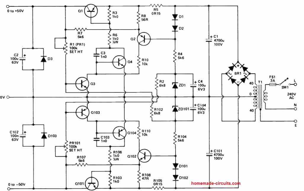
To support these output levels, the secondary of T1 should have a rating between 4.5 and 5 amperes. Furthermore, it includes comprehensive current limiting protection.
This circuit is well-suited for applications involving audio power amplifier modules that demand supply rails of up to 50 volts. Please take note that R8 should be set at 47 ohms.
NOTE:
Q1 IS MJ2501
Q2, Q104 ARE BC448
Q3 IS BC182
Q4, Q102 ARE BC447
Q101 IS MJ3001
Q103 IS BC212
D1, D2, D101, D102 ARE ANY GENERAL PURPOSE SILICON DIODES
D3, D103 ARE 1N4002
ZD1, ZD101 ARE 5V6 400rnW ZENERS
BR1 IS 600V 10A BRIDGE RECTIFIER



Questions & Answers
Thank you sir I was planning build your 50V 10A power supply circuit but it is very difficult to use bc447 bc448 transistor. so please let me know witch transistor is suitable for it thank you
No problem Manjula, If you are unable to find them you can use BD139, BD140 instead.
https://drive.google.com/file/d/1iwCMqNqrPQnhr9ojgp_AM84tJCCK3n2B/view?usp=drivesdk
good day, sir, I wanted to make a 0-50 V 10 A power supply for two I attach a link for short circuit protection for which I would use irfp 9140/140 ask if it is ok, say that it is needed as well as a voltmeter and ammeters
Again, sir, I’m wondering if 10 A in this dual circuit, perhaps regulated to 1, can be effectively and safely supplied even with a good trimmer. It was posted near the top of the website that it would require voltmeters and ammeters (for these, I bought a center-zero one) and short-circuit protection (I provided a non-openable link and downloaded an image, but perhaps the site doesn’t allow it) consisting of two MOSPOWERS that block the current flow in the event of a short circuit. I’m waiting for the material to arrive to make it work with a 24/24 V 3.75 A transformer to power a pair of Semelab BUZ 900/906 amps. I have problems with other types of power supplies. I’m really hoping for your comment, sir. Best regards.
Hi Carlo,
I think the following design would suit your application well:
https://www.youtube.com/watch?v=ZVlyDGTLxUI
We can two of these units to make a dual supply circuit…
Good morning sir, on YouTube I can’t read or the abbreviations of all the components of the short circuit protection are missing. If possible, have a link to this diagram. I’m wondering if instead of the IRF 9540, an IRFP 9140/140 wouldn’t be better. Best regards.
Carlo, please try the following basic design first without current limit, only voltage regulation…if it works correctly then we will move ahead and add a current limit to it:
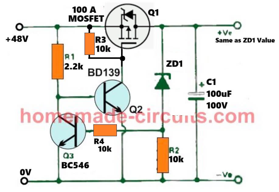
Good day sir, can you provide me with the codes for a complementary pair of 100A 150V Mospower batteries that I can’t find?
Carlo, you can try these:
IRFB4115PBF (Infineon)
IXTH50P10P (IXYS)
….please make sure to add a 15V zener across R3.
Hi Carlo, your google drive link is not on shared mode, so it does not open for me.
good morning sir, I had posted the question on the acronym of two complementary mospower for short circuit protection but they do not necessarily have to be to 247 but are dissipated to 220 also fine?
Sorry Carlo, I am not able to understand your question correctly…please explain it again..
ha già messo la risposta grazie. IRFB4115PBF (Infineon)
IXTH50P10P (IXYS). ho provveduto a acquistare maggior parte materiale che sto aspettando anche da AliExpress le farò sapere ma ci vorrà tempo, saluti
No problem Carlo, let’s hope the parts arrive as ordered…all the best to you…
Mr. Swagatam,
In the first example (this allows for up to 10 amps), you indicate that R4=0.6/Maximum Current Limit (10 amps), Wattage = 0.6 x Maximum Current Limit (10 amps). Am I correct that I need a 0R06/6 watt resistor? I’m assuming the resistance is 0.6 ohms/10 (amps) to equal 60mOhms or 0.06 Ohms. Am I calculating this correctly?
Thank you Don,
0.06 Ohms is correct, and this must be rated at
0.6 * 10 = 6 watts.
And you can make it by using many 2 watt or 3 watt 1 ohm and other similar assorted resistors in parallel.
Hello Mr. Swagatam,
In the Bill of Materials list, you indicate that D1, D2, D101 and D102 can be any “general purpose silicone diodes”. Do you have a preference or suggestion what would be best to use? Would using additional 1N4002 work well? While my goal is to operate the power supply at 35V, I will be using all 10 amps to power 2 amplifiers using the TDA7294V chips. I want to ensure that all my components are robust enough to handle the voltage and amperage that will be required.
As always, thank you for your wonderful articles and instructions. I appreciate you!
Hi Don,
those diodes can be any low current rectifier diode such as 1N4148.
These diodes don’t have to handle high current so any ordinary low current rectifier diode will work…
pls can you help with a dual variable power supply circuit that I can use a chopper transformer since I has a 19 volt chopper transformer
can I use chopper transformer without rewinding as fresh
Here’s a chopper transformer circuit with dual DC output:
https://www.homemade-circuits.com/smps-2-x-50v-350w-circuit-for-audio/
How do you eliminate the .6V minimum. I need a true 0 to 30 Volts?
Hey there Ned Sheats! It’s me, Seth, from the Face Book forum! I just needed a 0 to -50 or maybe 0 to -75 VDC supply for a grid bias supply for a vacuum tube tester that I am building. I also need to put a 1KHz to 5KHz AC signal onto the grids. The 5KHz volt meter will set me back some but… If you need it, and I do. Cheers, mi amigo! Good luck. P.S. I do have some wonderful old regulated tube PSUs that have 0 to -150 VDC bias outputs. Some of them have very little current available.
In the first diagram, please replace the D1 and R7 with short circuit.
Hi mr. Swagatam.
I have a problem with making an overload / short circuit protection for a dc-dc buck converter output.
I want to make a bench power supply but this buck converter with lm25116 control ic, it dose not turn off the output in short circuit or overload conditions and this causes a damage to the output mosfets.
The input voltage is 26v.
Te output voltage is 1v to 25v and the current is 0.1A to 15A.
The dc-dc buck converter is 300w 20A.
Help me with a proper overload / short circuit protection circuit.
Hi Talal,
The LM25116 IC has all the voltage and current control features available in the IC.
You have to configure a current sensing resistor in series with the source pin of the low-side MOSFET, and then connect the junction to the CSG pinout of the IC.
Full information can be obtained from the following pdf:
https://www.ti.com/lit/ds/symlink/lm25116.pdf?ts=1722424800958&ref_url=https%253A%252F%252Fwww.google.com%252F
Hi swagatam What you thinking for output 20 amper give circut design also ıts give adjustable voltage.
Hi Enes, 20 amp is too high and is not recommended for this type of circuits due to high heat dissipation.
Hello Swagatam . I want to make a 0-60V 20A regulated power supply, can I provide this in the circuit you have given?
Hello Inesta, as we all know the biggest drawback of all linear regulator power supplies using transistors as explained above is high power dissipation, which is proportional to the difference between the input and the output voltage levels.
So at 20 ampere the heat generated on the transistors will be immensely high at low output voltage settings, therefore I cannot recommend you the above design.
Swagatam If you want to lower the power dissipation then use transformer wingdings to lower voltage according to your required Voltages………….
Thanks Zia, that’s right, we can use tapped transformer secondary winding and select it according to the output requirements, to keep the dissipation on the BJTs low.
Hi.. swagatam
I will like to build this power supply +-50v 0-10amps
* Can I Change the variable resistors value to a common value like 5k or 10k ? Will they be any effect when done?
* How can MOSFET be used in this circuit how do I use it?
* will they be any effect?
Hi Davis,
The variable resistors can be replaced with fixed resistors after calculating their values appropriately.
You can replace T1 with MOSFETs, however if a MOSFET the minimum output will not be lower than 8V. Make sure to put a 12V zener diode across gate and source of the MOSFETs.
MOSFET will allow higher current output compared to BJTs.
Ok, I mean can I use a 5k or 10k variable resistors for both P1 and P2 instead will they be any effect on the voltage or current? Because it will difficult to get 2k5 variable resistors here in my electronic store.
Using MOSFET could have been better but since you said it minimum output voltage can’t be less than 8v then I think I will just go for the BJTs
But can’t it be 4v minimum because of it gate voltage? What if I use 6v or 4v zener diode?
Yes, you can use 5k potentiometer in place of the 2.5k, although the adjustment range might not be from start to end of the rotational dial rather might end somewhere in the middle of the travel.
Sorry, it is actually the maximum voltage that might be 6V lower than the maximum input supply voltage, meaning if the maximum supply is 50V, then the maximum output that can be achieved using a MOSFET will be around 50 – 6 = 44V
Ok,that makes sense now using FET, but will the voltage be 0v when voltage knob is turn down to 0 ?
If I will be using FET in place of BJT how will it be connected ? and what resistor value should be at the gate and gate to source
How do I connect FET?
Yes, almost 0V should be achievable.
I think you can modify the second diagram as explained in the following article:
https://www.homemade-circuits.com/0-300v-variable-voltage-current/
Okay…
If I will be using FET in place of BJT how will it be connected ? and what resistor value should be at the gate and gate to source
How do I connect FET?
Please see the second circuit as given in the previous link. You can build the same design for fulfilling your requirements.
Dear Sir, In the 0-50V dual PS, where do I take connection for the Digital volt(100v) and amp(0-10A) meter? size:48x29x21mm
Hi Parthasarathy,
you can connect the voltmeters parallel with C2 capacitors.
You can connect the ammeters, one in series with the + output and the other in series with the – output of the power supply.
Very kind of you.