The post describes a simple but extremely versatile 100 amp, variable voltage power supply circuit using just a few BJTs in parallel and in a common collector mode. The idea was requested by Mr. Andre.
Technical Specifications
Hello Swagatam, I was wondering if you could possibly assist me. on the blogs I have seen some diagrams for simple variable power supplies.
Firstly I know very little about electronics, but with a shopping list and a diagram I am sure I would be okay.
I would like to build a simple variable power supply with an input of 220/240 volt ac and an output variable voltage of approx. 1.5V to approx. 15V and a variable output current of up to approx. 100A.
I have started zinc electroplating as a hobby (have sweaty hands and want to protect all my tools) the chemical company gave me these as a more or less dependant on my zinc plating bath size.
At the moment the little 6V 8A Ryobi battery charger works for a few minutes, overheats and cuts out till it cools down again. I would really appreciate any assistance you could give me on this.
Many thanks
Andre
The Design
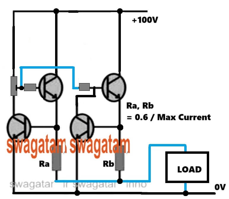
A very straightforward circuit design for the proposed 100 amp variable voltage power supply can be witnessed in the following diagram.
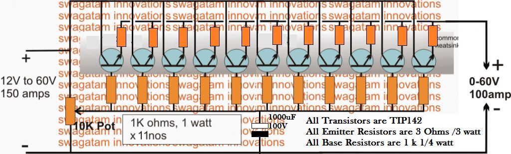
The design basically utilizes a common collector or an emitter follower topology for implementing the operations, by incorporating just a few Darlington power transistors, some resistors and a pot for varying the output voltage.
As can be seen in the diagram, the collectors and the emitters are all joined in common across each other while the bases are made into a common line via individual limiting resistors.
The free ends of these resistors are joined together with a pot across the negative line of the circuit, which determines the voltage regulation at the output of the circuit.
For acquiring more current, more number of transistors may be added in the design, and for reducing the output amps, these may be simply deducted from the configuration.
For inputs above 50V the pot must be upgraded to a high wattage type to sustain the high voltage across its terminals.
All the power devices must be mounted over a common aluminum heatsink without any mica isolation, so that the dissipation is shared uniformly across all the devices and a thermal runaway situation is prevented.

Questions & Answers
Wow, thank you Bro, it helps a lot…
You are welcome Ruel!
Hello. Thank you for this simple yet practical circuit.
We know that the base resistor is used to limit the collector current and is very necessary. But the question is, what is the need for the resistor in the emitter path? Suppose a current of 10 amps passes through each emitter branch. Considering the resistance of 3 ohms, the power dissipated on the emitter resistor will be 300 watts. How is this justified? Thank you for your attention.
Yes, that’s right, in that case we can add a dedicated current limiter stage with each power transistors in the following manner, then the current limiter resistor values can be significantly minimized:
Hello, i am interested in designing a 240vac input 12vdc 150-200A load dependent power supply and this seems to be the place to get it figured out. All help is appreciated. Especially with the transformer selection portion. The project is actually converting 240vac 50hz to dc then using an automotive inverter to get 1500w 120v 60hz. I really want some lor coffee in europe and don’t want to ruin my 60hz machine with 50hz line. Thanks again.
Hi, thanks for your question.
I don’t think the inverter is actually needed, it appears to be an overkill.
Instead, you can simply use a 240 AC to 120 AC 1500 watt transformer for the required conversions.
Let me know if it makes sense.
No this does not make sense because i have ruined several appliances using step down transformers. Basically anything with a motor.
Hi, the transformer method is the best practice and the recommended method, because it will perfectly transform your 220V AC into 120V AC or vice versa.
However, you must ensure that the transformer wattage and voltage specifications are correctly matched with the load. Otherwise the voltage can drop causing problems with the working of the load.
I am sorry, I think I missed the frequency part. The transformer will not be able to transform the 50 Hz frequency into 60 Hz, which can be a problem to a inductive loads like motors.
The circuit is simple and effective
I have a problem with short circuit protection at 50V output.
It does not respond fast enough even if I limit the current at 2.5A
Even a relay current cut off circuit is to slow
The TIP142 blows instantly
Any recommendations?
Regards
Naude
You can add a current control feature to the above design as shown below. The current control transistor can be a 2N2222. Make sure to add a series 2.2K resistor with the potentiometer. The current limiting resistor RX can be calculated by solving the formula, RX = 0.7 / Max current.
Dear Swagatham,
In the given circuit bc547 is used. This is very low current BJT. Can we use transistors like 2N6287 (100 v(Vcb & Vce ; 20A Ic) or TIP 142 itself (10A Ic) ?
Dear Suresh,
I cannot see any BC547 in the above diagram, can you please specify which schematic are you referring to?
Sorry ? 2N2222 in the modified diagram with short circuit protection.
Maximum Collector Current |Ic max|: 0.8 A
The 2N2222 is configured as a current controller which has to handle only the base current of the TIP142 which is not more than 50 ma or maybe 100mA, so it can easy handle that.
Dear Swagatham, Thank you for the reply. I now understand the process. I was thinking that the 2n2222 (or its substitute) needs to handle the full load current (Say 10A). Anyways, I made a unit with two TIP142 in parallel and TIP 135C (25A) in place of 2N2222 you suggested. (may be I should try 2N2222). It works fine. The 10K gets a little warm. A wirewound pot may be a better choice , I think. I used 0.5ohm 25 watt resistance for Rx. There is some voltage drop when load is connected (tried a DC motor. it takes 0.335A and the voltage drops from 12 to 8.5. Do you think this could be improved ?
Thank you Suresh, Glad you understood the working of the current limiter stage and could successfully build the circuit.
With a 0.5 resistor for the current limiter resistor, the maximum load current would be restricted to:
I = 1.2 / 0.5 = 2.4 amps.
If your load is not consuming more than the above current then the voltage should not drop.
However, if the input current is lower than the load current requirement then the voltage will drop.
You can temporarily remove the current limiting stage and check whether the voltage is dropping or not, that will prove whether the current limiting stage is causing the voltage drop or not.
Dear Swagatham, Thanks a lot. on the test digital meter, it was showing only 0.335A. Let me check as you suggested. I also collected metal 2N2222 too just for testing and understanding the behavior of the circuit with both the transistors (2N2222 vs TIP 35C). plus a bigger cap too.
Thank you Suresh, for updating the info! Make sure your input current is optimal, as per the load requirements, otherwise the voltage will drop. All the best to you!
Dear Swagatham, Thank you.
One issue I noted with this is voltage creeping up or down. One needs to wait for some time for the voltage to stabilize. Then again one has to adjust since the voltage drops according to load.
Another thought ! can’t we use an opamp to control the output BJT / MOSFET ? will it not provide a better & safer control ?
[ I blew three TIP 142 today- investigating why this happened ].
Dear Suresh,
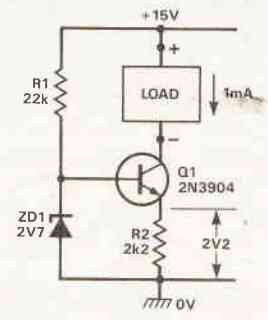
If the voltage drop is happening due to lack of current to the load, then even an opamp regulator will not be able to regulate it.
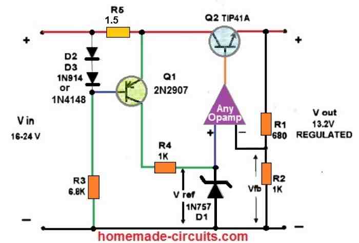
For an opamp based regulator you can refer to the following diagram:
For more details on transistor voltage regulators, you can refer to the following article:
https://www.homemade-circuits.com/simple-voltage-regulator-circuits-using-transistor-and-zener-diode/
Dear Swagatham,
“If the voltage drop is happening due to lack of current to the load,”
Oh no! I use a 65V 6 amp transformer..
thanks for the links. I shall check them.
This one looks very good. https://www.homemade-circuits.com/adjustable-0-100v-50-amp-smps-circuit/
OK, 6 amps looks quite adequate for your load, you can try the op amp version, if the current still drops then the problem could be with the transistor base resistor, which will need to be reduced further.
Dear Swagatham, Thanks for the suggestion. I was thinking the same. I shall check this.
You are welcome Suresh!
Thank you. Will try
I looks as if with the 2k2 there my output will only be 46V if my input is 56V and I need at least 50V max
OK, in that case put the 2.2k resistor in series with the wiper arm of the pot, just after the arrow head. This is actually to safeguard the 2N2222 current limiting transistor. However I think 2N2222 is rated at a maximum of 40 V, in that case you can use some other NPN transistor which can handle upto 100V.
Of coarse! I see. Thank you
I will report back
Hi
I had time to test the current limiting today
Like all the other methods it does limit current what it was designed for but on 50V with a dead short on the output it is just not fast enough and blows the darlington collector emmitor
Hi, maybe the current limiting resistor value was not appropriate, you can try increasing the value of the resistor, that might solve the issue. If not then it is unfortunate.
I am sorry to say that this is not a good circuit and its construction should not be recommended. Unbalance of collector current of transistors followed by thermal runaway is unavoidable
Emitter resistors are provided to avoid thermal runaway. The circuit may not be efficient but very easy to build and implement.
I am trying the 100amp power supply and it would not work , is they any one who got it to work
What kind of problem are you facing? Try with 10 amp first and check the response.
I am getting the same input voltage at the output and not adjusting, what I did to get it to work I place the input voltage on the base, and the base resistors on the collector and got a good variable voltage on the emitter but it cannot handle a load, it falls off from 13.8v to about 5v.
If the voltage is not adjusting then something might be be wrong with your transistor or the connections. Try with a small load at the output and check whether it is adjusting or not.
Hi Swagatam,
Good day to you. I am Manjunath. I have read your articles and the answers are good. I have a question that is how to convert DC 5Volts 3 Amp from the Battery pack of DC 12Volts 90Amp? Please give me your ideas for me.
2nd question is how to make a charger (Input AC ~220 Volts) for a Battery pack of DC 12Volts 90Amp.
Thank you Manjunath, for liking my articles.
You can probably try customizing the following circuit for boosting 5 V to 12V
You can adjust the number of turns of the coil to test the output response.
For the charger you can simply refer to the following article:
12V Battery Charger Circuits [using LM317, LM338, L200, Transistors]
Hi Swagatam,
I am asking about the buck converter from 12volts 100 Ah battery to 5v 3A., not for the boost converter. If you have any ideas on it please share them. You are only the person who can help me…Please help me on this.
Hi Manjunath,
OK for a buck converter circuit you can customize the following circuit according to your own needs:
PWM Solar Battery Charger Circuit
If you have any further queries, please let me know.
Hi Swagatam,
I am always inspired from your post as they’re always helpful and great.
This circuit is interesting i want to test it as i have a SMPS 12v and 100amps. But one thing is confusing. In the given above circuit you used 11 transistor as each can bear 10A so overall 110A safe range for 100A.
If i connect my SMPS with it and for example voltage is decreased using the pot (given in your design) wouldn’t be the current at the output become high enough to blow transistors immediately.
I see that the circuit doesn’t have protection against overload and short circuit at the output. Please guide me if anything i can add or modify for it. Many thanks & Hats off always
Hi karan,
The number of transistors are actually not accurate, for 100 amp current there must be at least 20 nos of TIP142. More the numbers cooler will be the transistors.
The current through the transistors will depend on the load, not on the voltage adjustments. But yes wider input/output differential will cause the transistors to heat up a lot, that’s the drawback of all linear power supplies. To correct this, the input voltage range from the SMPS must be reduced appropriately.
Protection has not been provided, you can add a current limiting by adding a common 2N2222 limiting circuit network, as explained in the following concept.
2 Best Current Limiter Circuits Explained
Hi
I want to DIY Electroplating IGBT controlled full DC Rectifier 0-30 Volt DC and 500 Amp. Please help me out I saw some readymade circuit on Aliexpress but without full diagram
Hi, sorry, presently I do not have the requested circuit with me…
Hi Swagatam. I am searching a circuit which I can use as battery charger and as welding machine. I mean, by the primary of the transformer regulate the current and voltage. Where I can set up voltage for battery charger and charging current. I I need a welding machine use it with this application. Max voltage 40 or 48 and current from 30 to 1000.
Is it posible to design?
Hi Rafael, 30 to 1000 amp looks too high, and will require special mosfets to control the current….the transformer primary cannot be used for regulating the current.
If possible I will try to find a suitable circuit for you soon…
hello sir,
I need 5 volt dc and 100 amps power supply circuit diagram so please send me as soon as possible and send me your phone phone number for further conversation.
thanks
Hello Mohd, sorry I do not have a 5V 100 amp smps circuit with me at this moment…
how is this circuit going to give 100 amps, when you have 11 resistors in parallel of 3 w each, 10 amps makes more sense, but how is it going to pass 9 amps through a 3ohm resistor and dissipate 3 watts ???????
It is just an idea, you can customize it by reducing the resistor value, or add more number of transistors stage in parallel.