The post presents a discussion regarding the troubleshooting of a 4047 IC based inverter output voltage drop problem on connecting a load. The solution was requested by Mr. Isaac Johnson.
The Issue
Good day sir, I am a reader of your blog and an electronics hobbyist.
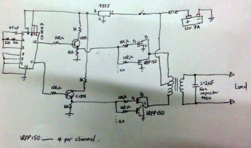
I constructed a square wave inverter with a filter capacitor(ceiling fan capacitor 2.2uf 400v) at the transformer out. I noticed on no load, i sometimes get 200-215v but when i connect a 200w bulb the output Voltage drops to 186v. I used a 12v 7A battery.
Pls is the FET not conducting fully? I get around 2.5v at pin 10 and 11 of my oscillator. Even same at emitter load resistor feeding the Gates of my fets (is the volt too small to cause the fets to switch fully?).
Pls check my Circuit, and Advice me. Also is the 8v regulator necessary? If no, wont the battery current damage the cd4047 (oscillator) and c1815 (driver) directly? My transformer is gotten from a old 2kv ups so it cant be having regulation issue or been small. Pls assist me.
Isaac Johnson.
Solutions:
The battery Ah is way too insufficient for handling a 200 watt load. In order to achieve 200 watts of power without dropping the output voltage, a minimum 40 AH would be required from the battery.
The FEts are conducting correctly and fully, the 2.5V is roughly the 50% of the supply since the outputs are switching at 50% duty cycle, the peak voltage would be close to the supply DC of the IC.
The voltage regulator shouldn't be removed as it's presence will not harm the circuit in anyway, but should be replaced with a 12V (7812) regulator for a better response.
The 1K at the collector can be removed (shorted), and the emitter resistor should be replaced with a 1 K.
The transformer primary must be rated at slightly lower than the battery voltage for optimal performance, for example with 12V battery it could be a 9-0-9V rated. This will ensure a normal output voltage within the required range even while the battery voltage drops to a relatively lower level.
Feedback from Mr. Isaac
Thanks alot for that urgent response and eye-opener. I am cleared.
Pls, in a Circuit such as the inverter oscillator section Where i used a 8v regulator, what would be the effect if i were to connect the circuit directly to a battery say 12v 100A?
Will the circuit draws only her required current (mA) needed to function or will the battery (high Amps) damage the i.c's?
From my little basic knowledge of electronics, it should be ok having it connected directly to the battery irrespective of the Amps provided the i.c's rated Voltage is not exceeded. Pls correct me if i am wrong.
Am having doubts in that regard.
Thanks so much.
Isaac Johnson
My Reply:
Since the IC4047 is specified to work with higher voltages than 12V, it won't affect its performance even if no regulator is used, but a regulator is always recommended for better safety. Amp of the battery becomes immaterial as long as the IC maximum voltage rating is not exceeded.
Higher Ah values will not affect the circuit at all. The inverter will consume only what it is supposed to consume, according to the output load current specifications.


Questions & Answers
can an inverter carry both pwm and output voltage regulator circuit at the same time? Will they inhibit one another?
Yes that’s possible, but automatic correction won’t be required if the inverter produces fixed PWM
Good day sir Mr Swagatam, Please sir from the above circuit of Mr Isaac John where he connected 2.2uf/400v capacitor at output inverter.
1.Is it Possible to connect 2 to 3 of that capacitor in parallel at the output.?
2. What is the effect by connecting 3 capacitor in parallel?
3. If yes that is possible, is there any disadvantage to the inverter?
Thanks so much sir for the quick responses so far am very much greatful thanks.
Hello Godspower, if you connect significantly high values of capacitor at the output of a square wave inverter then the standby current consumption of the inverter may increase to a much higher level, causing unnecessary depletion of the battery even without load.
A single 2.2uF is fine, anything higher than might start causing unnecessary battery current drainage.
The capacitor helps to carve the square wave corner edges to provide a sine wave like appearance.
Thank you sir I appreciate, now I understand sir.
You are welcome!
Good day Mr Swag. Please what is the functions of 2.2uf/400v capacitor used at the output of the transformer, by Isaac John in his above circuit. Thanks in advance.
Hi Godspower, the capacitor is placed to blunt of the square waves and produce a close to sine wave like output
Thank you sir.
Hello Swagatam,
I have a 12v inverter i put together from a circuit diagram which uses irfz44n mosfets. When i used just 2 mosfets, and connect a 100w bulb it glows almost very full but when added more mosfets to make it 10 as the diagram specified and connected the 100w electric bulb, it is no longer bright. The issue is that volttage drops when i connect a load.
What could be the problem I am not sure i know how to attach an image here
Hello Joe, Mosfets work only like ON/OFF switches, adding more mosfets in parallel simply means adding more switches in parallel, so that must not affect the load current, in fact more mosfets would mean more current to the load.
Instead of connecting all the 10 mosfets together you can connect them step wise. First try with 4 mosfets, then 6 and then 8…that will help you to know exactly which mosfet is creating the problem.
hi ,
i want to run 0.5 hp induction motor with the inverter. but i dont know which mosfet is right for this purpose. i want to use irf3205( 55v 110amp). if i use this mosfet with CD4047 inverter circuit. is this possible to run 0.5hp motor. i make that circuit with another ratings of mosfet, problem is that when i connected the load ,voltage decreases simultaneously from transformer output, please give me that solution, and what will be the appropriate size of transformer when i run the motor.
thanks.
Hi, the MOSFEt is OK, just make sure to mount it over large heatsinks.
the transformer wattage should be at least 500 to 600 watts, battery must be 500 Ah if it’s 12 V, and 250 Ah if it’s 24 V.
If 24 V is used, make sure to supply the IC through a 7812 IC
hi,
actually i want to use power supply 12v 60amp.that means 720watt. motor rating is 350 watt. so is it possible to run that motor.?
thanks
yes that’s possible, but if you have AC mains access, then why not use AC mains directly for the motor??
hi,
actually my final year project is VFD system. for this reason i try to make that. i change the frequency using bilateral switch with various capacitor value and also micro-controller. but i will make the frequency range 30hz to 50hz. may be the motor does not run below 30hz frequency.for this reason i try to know about many things from you.because your are most intelligent of this site. so thank you again for your helping.
OK, no problem. I’m happy I could help you!!
hi sir,
this circuit is good .but i have some problem for setting frequency. can you pls give the calculation for measuring RC value.
thanks
Hi Milon, you can use 0.1uF for the capacitor and 56K for the resistor to get around 50 Hz frequency.
Really thanks to you for immediate response,
sir,
actually i want to make variable frequency using bilateral switch(cd4066 ic) with various capacitor value. already a designed that.i want to drive 320watt induction motor.for this circuit (cd4047), how many ampere needed for driven that motor. and how many frequency is lower for driven that motor.that means what is the lowest frequency for driving motor.
Thanks
Thanks Milon, the current and the frequency of the motor should be referred from the specifications of the motor, it is not safe to judge it randomly, so please check the spec sheet of the motor for the mentioned info.
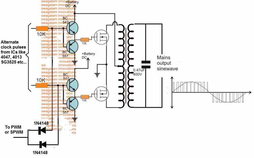
hello in the diagram, there is the addition of two trasitores 2CS 1815, this procedure aims to increase the wave to add more FETs ? please reply by e- mail:
kellonciklone@gmail.com . thank you
It could be for isolating the IC from the mosfet and present a better charge/discharge path for the mosfet gate, however, connecting the gates to the collector of the transistors would make more sense than the emitters according to me…the emitters must be connected directly to ground in that case.