In this post I have explained a simple yet very useful 0 to 50V dual power supply circuit which will enable a full 0 to maximum dual voltage +/- control of the input power supply DC. It also includes a wide range current control feature right from 0 to 10 amps. The idea was requested by Mr. Tamam.
Technical Specifications
It was my long term dream to build a 2 channel power supply for personal use, I have seen a lot of circuits, but those does not fit my criteria.
However, please take a look at the following requirements and let me know if its possible or not, if possible I will be the happiest person in the world.
1. Output voltage range: -50V to 0V to +50V ( must be adjustable by individual channel )
2. Output Current range: 0A to 10A ( must be adjustable by individual channel )
3. Output would be Duel channel, means total 6 outputs,
Channel 1 (Positive, GND, Negative) Channel 2 (Positive, GND, Negative)
4. Power Supply Unit should contains 2 Voltmeters and 2 Ammeters (Analogue) for 2 individual channel.
5. Power Supply Unit must have short circuit protection and cooling fan featured and extreme heat protection.
6. I don't want to use any PIC or AVR, so please avoid those.
Money is not a matter here, I will spend continuously until above requirement meets.
Even If I need any custom transformer I will order and make it from our local area.
I have seen many ready made power supply in market but I want to make it by own hand. You just show me the way... please bro, I will be pleased to you for lifetime.
Thank you very much !!
Best Regards,
Tamam
For calculating the part values accurately, you can refer to this bench power supply article
Circuit Diagram
The Design
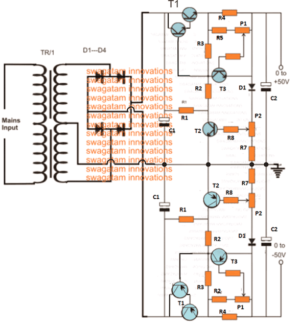
The basic design of the proposed 0 to 50V variable dual power supply circuit with 0 to 10 amp variable current facility is shown in the above figure.
The entire design is transistor (BJT) based and is virtually indestructible. Moreover it's equipped with an over load and over current protection features.
The two section included in the design are exactly similar with their configurations, the only difference being the use of PNP devices in the lower configuration while NPN in the upper configuration.
The upper NPN design is configured to produce a variable response right from 0.6V to 50V positive while the lower PNP section becomes responsible of producing an oppositely identical response from -0.6V to -50V output.
The Transformer Specs
The maximum limit could be suitably changed simply by changing the voltage rating of the transformer. However for higher voltages you may have to appropriately upgrade the BJT voltage ratings accordingly.
In both the designs, P2 executes the function of varying the voltage levels as desired by the user, while P1 functions as the current regulator and is used for adjusting or setting the output anywhere from 0 to 10 amp current. Here too the maximum rating depends on the selection of the transformer amp rating and may be changed as per individual preferences.
T1s in the both the sections become the fundamental part or the heart of the entire voltage control functioning in the circuit, which becomes possible due to the popular common collector configuration of the devices.
The other two active BJTs only help to implement the same just by controlling the base power of the T1s thus making it possible to adjust the thresholds to any desired user defined voltage and current levels, as per the ratings of the transformer or the input supply.
You may also like this LM317 based Dual Power Supply Circuit
Parts list
- R1 = 1K, 5 watt wire wound
- R2 = 120 Ohms,
- R3 = 330 Ohms,
- R4 = to be calculated using Ohms law, R = 0.6/Maximum Current Limit, Wattage = 0.6 x Maximum Current Limit
- R5 = 1K5,
- R6 = 5K6,
- R7 = 56 Ohms,
- R8 = 2K2,
- P1,P2 = 2k5 presets
- T1 = 2N6284 + BD139(NPN), 2N6286 + BD140(PNP)
- T2, T3 = BC546 (NPN) BC556B (PNP)
- D1, D2, D3, D4 = 6A4,
- D5 = 1N4007,C1, C2 = 10000uF/100V,
- Tr1 = 0 – 40 Volts, 10 Amp
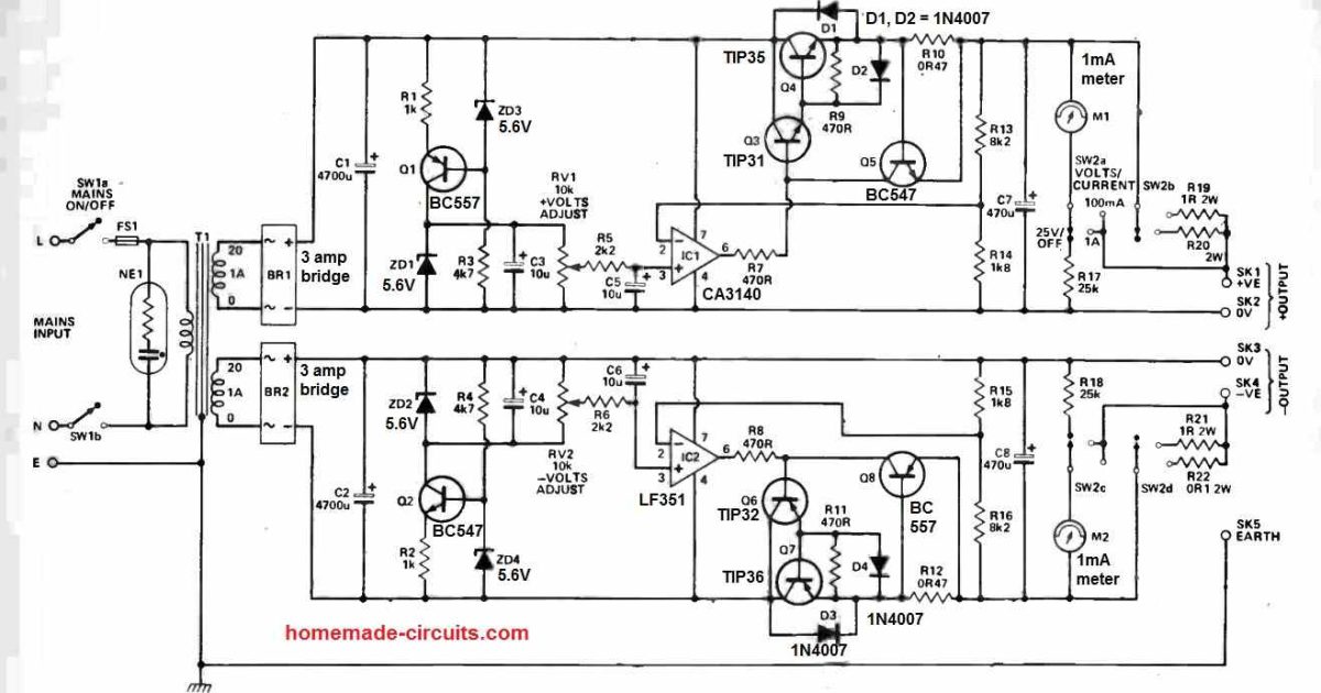
Using Op Amps and TIP35
Here's another accurate adjustable dual power supply circuit, for your reference:
Using MJ2501 and MJ3001
The versatile dual power circuit featured here can supply a maximum of 50 volts across its two output rails, capable of handling currents of up to 3 amperes.
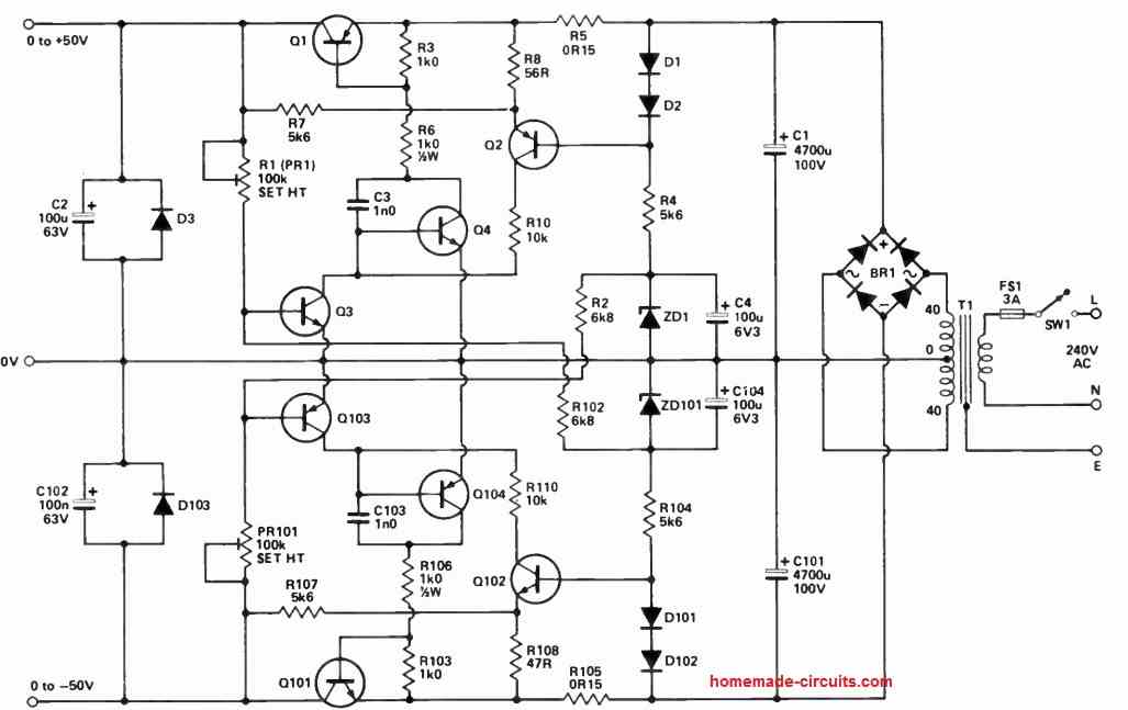
To support these output levels, the secondary of T1 should have a rating between 4.5 and 5 amperes. Furthermore, it includes comprehensive current limiting protection.
This circuit is well-suited for applications involving audio power amplifier modules that demand supply rails of up to 50 volts. Please take note that R8 should be set at 47 ohms.
NOTE:
Q1 IS MJ2501
Q2, Q104 ARE BC448
Q3 IS BC182
Q4, Q102 ARE BC447
Q101 IS MJ3001
Q103 IS BC212
D1, D2, D101, D102 ARE ANY GENERAL PURPOSE SILICON DIODES
D3, D103 ARE 1N4002
ZD1, ZD101 ARE 5V6 400rnW ZENERS
BR1 IS 600V 10A BRIDGE RECTIFIER



Questions & Answers
Dear Swagatam,You have connected C3 in reverse order in above circuit.It will charge in reverse polarity which will damage the capacitor.C3 positive terminal should be grounded while the negative terminal should be at negative voltage.Thanks
Dear Muhammad, thanks!
yes the lower caps were wrongly polarized, I have corrected the diagram now, please check it.
If I use a 0-36 V 3 Amp transformer for this circuit will the output still be 0-50 V and 0-10 Amp? I really need your reply sir its for our project thank you
That's impossible, in fact you will find a little less than 36V and less than 3 amp at the output
then what should i do sir to make an output of 0-50V and 0-10Amp? here in our town there is no 0-40V transformer sir.I hope you could help me sir . thank you
sir may i ask . if i use a 33.5V 10amp transformer what should i add to the circuit to make an output off 50V? here in our town we really cant find a 0-40V transformer. I'm hoping for your reply sir thank you
Hi,what rating of transformer did you use here? I mean the voltage and its current rating. Thanks!
It can be a 50-0-50V 10amp trafo.
Will a transformer with a lower current and voltage rating still for this circuit say 24-0-24, 3amp? If so, are there modifications that I have to do like have to change vlaues of some resistors or change a transistor etc? Thanks!
any voltage and current can be used with this design, depending upon the maximum tolerable rating of the transistors…….no modifications would be required
Just to add to my question, what pnp transistors should I use to the lower ciruit?
MJ2955 for the PNP and 2N3055 for the NPN
and BC556 for the PNP and BC546 for the NPN
Dear Swagatam,
Can you recommend a short-circuit protection for this circuit?
Respectfully,
Ramunas
Dear Ramunas, the above design is already short circuit and overload protected.
Dear Swagatam
MJlorton has added a link of your variable circuit diagram uploaded on brighthubengineering.com in his video series of how to build a variable power supply and i feel proud of looking at it. i am in search of a versatile digital variable power supply diagram with the specifications of 0-30v 0-5amp. i shall be highly obliged if you could provide me the same either existing diagram with required modification or you are requested which decent brand of variable bench power supply should i get for hobby electronics and laptop repairing. Thanks a lot
Dear Gowhar,
you can probably try the following design, this looks exactly suitable as per your required specs:
https://www.homemade-circuits.com/2016/01/universal-variable-power-supply-circuit.html
Dear Swagatam,
I can use SC1815 and SA1015?
Respectfully,
Ramunas
for which transistors do you want to use these?
T3 and T2
If both are NPN and rated at 60V (collector V) then you can use it
Hi swagatam sir
I need 12v-3amp power supply for my project
so please help me.
Hi jaydip, you can use an IC LM338 circuit for your requirement.
Hi sir, why there is so many pots in above circuit.Can you tell me the fuction of that 4 pots?, for example (pots 1 for adjusting voltages).And i want to use 24v 10 amp trafo for this, will this work?thanks sir
Hi Raihan, the upper positive section has two pots one for voltage adjustment and the ohter for current adjustment…the same is true for the lower two pots, which are used for the negative section of the power supply.
One more question sir, can i use same transistor for both upper and lower circuit?(i use 2n3055 for npn and mj2955 for pnp)thanks sir
yes the mentioned transistors will do.
Nice diagram… dear swagatam can u please put the diagram which is if i want to put digital volt and amp meter. Thanks before
Thanks GK, you can attach the ammeter in series with the positive output terminal of the circuit and voltmeter right across the +/- terminals of the output
thank you, but i cant see any pot, trimpot or vr to adjust the voltage and ampere,, how to adjust voltage and ampere on this circuit ?? maybe you can update the circuit coz im still learning how to build adjustable V and A symetrical ps with volt and amp meter. also i cant find where is the Tr1 on this diagram https://www.homemade-circuits.com/2012/01/how-to-make-versatile-variable-voltage.html as shown on the part list.
owh sorry my bad, coz u draw the pot just like regular resistor. ok i get it.
yes the one which are configured with arrows are the pots….
TR1 is the transformer
I WANT MY POWER SUPPLY FIXED THE VOLTAGE AS WELL AS THE CURRENT. MAY I KNOW THE P1 AND P2 VALUE SO THAT I MAKE IT 40v AND 10 A OUTPUT
Dear sir, Many thanks for this interesting circuit. I see that R4 is to be calculated by ohms law. Could you give me some idea of the calculation here? For example, where is the voltage and current being measured from and this what figures would go into the calculation? Sorry if this is a silly question, but I'm trying to understand how you would determine the value of R4 in any particular case (ie using a variety of transformer voltages).
Many thanks in advance.
Martyn
Thank you Martin, R4 can be calculated in the following manner
R4 = 0.7/max current limit
The value will cause the required triggering voltage at the base of the associated PNP, sufficient to force T1 OFF…this will happen whenever the max current limit is reached or whenever the load tries to draw a current higher than the set limit…it is not dependent on the transformer rather on the load
Many thanks Swagatam. That's a very helpful explanation of what is happening.
Best wishes.
Martyn
You are welcome Martyn!!
Please help me
I want the maximum current 10A
what r4 must i use?
Thanks
R4 = 0.7/10 = 0.07 ohms, 10 watts
use 0.1 ohms/ 2 watt and 0.22 ohms/2 watt resistors in parallel
Thank you
Sir may you please tell me the watt of all resistors used here and also types of capacitors ??????
sir may u tell me watt of all resistors and types of capacitors used here??
All are 1/4 watt except R4.
R4 watt = 0.6 x maximum current selected for the output
all caps are electrolytic
which one is r6 and which one is r8? please clarify these. thanks
WHICH ONE IS R6 AND WHICH ONE IS R8? PLEASE CLARIFY THESE, THANKS
WHICH R4 WILL A NEED FOR A 40 VOLTS 3AMPERE OUTPUT???
AND CAN YOU ACTUALLY POST THE ENTIRE FORMULA OF OHMS LAW TO
CALCULATE BOTH THE OHM VALUE OF R4 AND THE WATTS VALUE OF IT
PLEASE I WILL LIKE TO SEE THE FORMULA IF ITS NOT TOO MUCH
TO ASK, WE CAN ALL LEARN MORE IF YOU POST IT, THANK YOU VERY MUCH
I have updated the formula in the parts list
Hello everyone…
I am very anxious to make this beautiful source.
Would anyone have the layout (pcb) to make available?
I still do not have enough skill to do the layout (I still get there).
Thank you very much!!!
sorry PCB layout is not available, however it does not require one since it can be easily built on a general purpose board, with some patience.