In this post I have explained the circuit for a simple, universal capacitive discharge ignition circuit or a CDI circuit using a standard ignition coil and a solid state SCR based circuit.
For an audio/video explanation, you can watch the following video representation:
How Ignition System in Vehicles Work
The ignition process in any vehicle becomes the heart of the entire system as without this stage the vehicle just won’t start.
To initiate the process, earlier we used to have the circuit breaker unit for the required actions.
Nowadays the contact-breaker is replaced with a more efficient and long lasting electronic ignition system, called the capacitor discharge ignition system.
Basic Working Principle
The basic working of a CDI unit is executed through the following steps:
- Two voltage inputs are fed to the electronic CDI system, one is high voltage from the alternator in the range of 100 V to 200 V AC, other is a low pulse voltage from a pickup coil in the range of 10 V to 12 V AC.
- The high voltage is rectified and the resultant DC charges a high voltage capacitor.
- The short low voltage pulse drives an SCR which discharges or dumps the capacitor's stored voltage into the primary of an ignition transformer or coil.
- The ignition transformer steps up this voltage to many kilo-volts and feeds the voltage to the spark-plug for creating the sparks, which finally ignites the combustion engine.
Circuit Description
Now let’s learn the CDI circuit operations in detail with the following points:
Basically as the name suggest, ignition system in vehicles refers to the process in which the fuel mixture is ignited for initiating the engine and the drive mechanisms. This ignition is done through an electrical process by generating high voltage electrical arcs.
The above electrical arc is created through extreme high voltage passage across two potentially opposite conductors through the enclosed air gap.
As we all know that for generating high voltages we require some kind of stepping up process, generally done through transformers.
As the source voltage available in two wheeler vehicles is from an alternator, may not be powerful enough for the functions.
Therefore the voltage needs to be stepped up many thousand folds in order to reach the desired arcing level.
The ignition coil, which is very popular and we all have seen them in our vehicles is especially designed for the above stepping up of the input source voltage.
However the voltage from the alternator cannot be directly fed to the ignition coil because the source may be low in current, therefore we employ a CDI unit or a capacitive discharge unit for collecting and releasing the alternator power in succession in order to make the output compact and high with current.
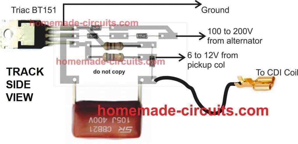
PCB Design
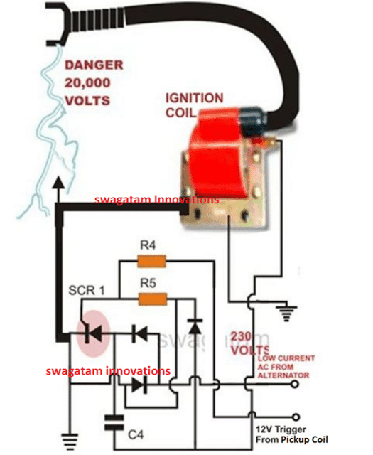
CDI Circuit using an SCR, a few Resistors and Diodes
Referring to the above capacitor discharge ignition circuit diagram, we see a simple configuration consisting of a few diodes, resistors, a SCR and a single high voltage capacitor.
The input to the CDI unit is derived from two sources of the alternator. One source is a low voltage around 12 volts while the other input is taken from the relatively high voltage tap of the alternator, generating around a 100 volts.
The 100 volts input is suitably rectified by the diodes and converted to 100 volts DC.
This voltage is stored inside the high voltage capacitor instantaneously. The low 12 voltage signal is applied to the triggering stage and used for triggering the SCR.
The SCR responds to the half wave rectified voltage and switches the capacitors ON and OFF alternately.
Now since the SCR is integrated to the ignition primary coil, the released energy from the capacitor is forcibly dumped in the primary winding of the coil.
The action generates a magnetic induction inside the coil and the input from the CDI which is high in current and voltage is further enhanced to extremely high levels at the secondary winding of the coil.
The generated voltage at the secondary of the coil may rise up to the level of many tens of thousands of volts. This output is appropriately arranged across two closely held metal conductors inside the spark plug.
The voltage being very high in potential starts arcing across the points of the spark plug, generating the required ignition sparks for the ignition process.
Parts List for the CIRCUIT DIAGRAM
R4 = 56 Ohms,
R5 = 100 Ohms,
C4 = 1uF/250V
SCR = BT151 recommended.
All Diodes = 1N4007
Coil = Standard two-wheeler ignition Coil
The following video clip shows the basic working process of the above explained CDI circuit. The set up was tested on table, and therefore the trigger voltage is acquired from a 12V 50Hz AC. Since the trigger is from a 50Hz source, the sparks can be seen arcing at the rate 50Hz.



Questions & Answers
Hey Swagatam Majumdar,
I have a Indian make yamaha Rx 135 (2stroke) and a TVS apache RTR 160.
These bikes have CDi's from the company itself.
Is it possible to enhance the performance of these bikes or a matter of any small cc bikes?
(P.S. I have read a lot about Performance CDi's and want to make one on my own. Please Guide me as this is very interesting topic for me)
Thanks,
Chinmay Bisht
chinmay20002@gmail.com
Hi Chnmay,
I have discussed one such circuit here:
https://www.homemade-circuits.com/2013/01/make-this-enhanced-capacitive-discharge.html
Although the circuit is a tested one and it definitely works, I am not sure if it would produce any adverse effect on the bike engine, you can give it a try under the supervision of a qualified auto electrician.
http://www.molla.org/DIY-CDI/SC-DIY-CDI-article-hires.pdf
That's a very interesting and useful link, thanks very much!
No, no specific limit.
when vehicle engine stops, the circuit also stops.
yes, if there are two spark plugs, then two CDIs can be used.
Hi sir… I have a honda dio 50cc 2 stroke scooter? Would this work instead of the stock cdi which has 5 pins and limiter?
Hi Ryan,
Yes the above circuit is a standard CDI circuit suitable for all 2 and 3 wheeler, basically it's an Indian, Bajaj 2E Rickshaw CDI circuit.
Hi Swagatam
What is the function of the diode connected across the primary of the ignition coil?
With cathode grounded, won't it obstruct the capacitor's energy from passing on to the primary of the ignition coil ???
Hi Abu-Hafss,
simulating the capacitor discharge pattern could be little difficult, however i am assuming the diode to be reversed biased, because practically the circuit is working perfectly so it means everything is right in the circuit.
It is also working without that diode !
did you test it?
Yes, the CDI of old model of Yamaha is 95% identical to yours, it does not have that diode.
the above circuit was designed by 'Bajaj" engineers, so the diode does work in someway to protect the longevity of the unit….because conditions in automobile electrical AC are too unpredictable, which show its impact in course of time and not immediately.
Hi I have a honda xr200 1981 the cdi is buggered will I need to get another one or is there a way to bypass this?
Do you mean damaged? it would be better to replace it then
Hey just surfing around the net looking at info on CDI design and implementation on the hobbyist level.
I have a 46 cc retrofit kit for a bicycle and it has given me 4 years reliable use even though it is very cheap engine that gets hard used.
I have had an alcohol still for a couple of years and have recently began running it on the head of the still 98% methanol 2% hydro-sol.
It has a magneto coil, I want a little more spark. I understand that i will need to implement a better cdi but also wonder if i can rewind the magneto coil or change the magnet provided there is enough room
yes making the magneto stronger would hep generating stronger sparks, so you can either modify the winding or simply procure a mobike magneto and replace it with the existing one,
Good day Swagatam Majumdar! I have a 2 stroke Yamaha L2GF 110 cc 1970's model that uses points. Can i convert it to cdi and use your circuit? Thanks..
Good day John,
Yes you can use the above circuit for your bike.
I am not clear on the trigger circuit, Can Hall Effect Sensor be added and a Transistor in place of the SCR.
hall effect/ transistor can be used for triggering the SCR, however it's more simply done directly through the AC received from the alternator 12V coil, as depicted across the diagram output terminals.
I have a need for an ignition system for a 6 cyl 2-cycle engine. 2 cylinders fire at a time, two times per revolution. i.e. that's 12 sparks per 360 degrees of crank rotation. I am quite gifted mechanically but alas, electrickery has me by the shorts. Can any reader offer assistance? Thanks, M8 (Mate)
you can try the following circuit,but could be difficult for you considering that you are very new in this field:
https://www.homemade-circuits.com/2013/10/universal-multi-spark-enhanced-cdi.html
Hello Dung,
It's quite easy, after making the above explained CDI circuit, you will just have to integrate the inputs to the indicated voltage outputs of the alternator.
Next, the C4 bottom link will need to connected with the free end of the primary of your ignition coil.
The other terminal of the primary coil will not require any attention as it would be originally connected to the ground of the vehicle.
That's all, this would conclude the installing of the explained CDI circuit
Hi Swagatam
I am making a CDI tester as per block diagram:
But, I am cautious that the pulse generator circuit might not be isolated from the 220VAC mains.
Your valued suggestions are requested.
Hi Abu-Hafss,
Do not use direct 220V, it can damage the diodes and the scr, you will need to isolate it using two step down trafos connected back to back
Hi Swagatam
Recently I physically made the 555 boost circuit with an output of smooth 600V.
The BJT network was removed. The Coil is super cool but the mosfet gets little warm.
However, when I feed the HV into the CDI………………..Nothing Happens.
1) If the triggering circuit is separated, the LED at the output shows perfect triggering. But when the output is connected to the CDI unit, the LED goes off.
2) If manual triggering is done with 9V battery/power supply, a faint single spark could be heard at the spark plug but not visible.
3) One point which might be or not important. The CDI unit is having 400V capacitor whereas, the boost circuit is producing 610V. Could this be the reason?
Hi Abu-Hfs,
What is the gauge of the wire that you have used? It should be selected appropriately for getting the required amount of current.
And the current from the power supply should also be rated high enough for the CDI coil to respond.
even 400V is high enough for acquiring 20000 volts from the CDI coil, so it's fine
I used 50 turns of 21 SWG (0.8mm) on a iron powder toroidal ring.
21 swg looks OK to me.
check the current through the coil and the BJT, this magnitude will actually decide the watts pushed into the ignition coil and will influence the sparks.
what is iron powder, do you mean ferrite?….ferrite core is a must for this application. iron core will only convert current to heat.
Hi Swagatam
I am operating this circuit with 12V-5A supply i.e. 60VA input.
The output is 600V, so the amperes roughly 100mA. This is just for idea. I will check the amperes and will inform you.
Ferrite toroidal rings are the black one whereas the iron powder toroidal rings are made with iron powder……more details could be seen here:
http://www.inductors.ru/pdf/Doc496_Ferrite&Powder_Core_Power_Inductors.pdf
I used Yellow/White ring.
Hi Abu-Hafss,
I think we are forgetting one thing, it's not the current that is important here, rather the voltage.
and it just requires an excess of 100V AC for the circuit to create powerful sparks across the high tension wire of the CDI coil.
Please refer to the first circuit given in this article, please see how it's configured:
https://www.homemade-circuits.com/2011/12/homemade-fence-charger-energizer.html
Hi Swagatam
The article you are referring involves 2 transformers whereas, my effort was to use a transformerless design.
I had that point in my mind that current is not an important issue here. For that particular reason, the output is around 600V as long as the input voltage is between 12V-30V !!!
Without the CDI, I have checked the capacitor gets charged within milliseconds. To connect to the CDI unit, I removed the capacitor + diode and connect the mosfet+coil directly to HV input of the CDI unit. (The CDI has its own diode and capacitor).
At the HV input the DVM set at AC is showing 6-7 volts !!! How can that be??? The CDI unit works perfectly in its place.
Hi Abu-Hafss,
I referred you the above circuit to indicate how the low current 220V input from an ordinary trafo works perfectly to produce the required 20kv sparks at the output of the CDI coil
I am afraid removing the diode capacitor network will not help, it's required for the proper functioning of the design, may be because it operates by charging and releasing the capacitor stored energy only when the capacitor charge reaches some optimal point.
The think the CDI coil or any such trafo responds best when bursts of high voltage are dumped in their primary winding instead of a continuous frequency.
Hi Swagatam
It seems to be quite difficult in getting the 555 boost circuit to work as HV supplier to a CDI. I have spent many hours but, not successful.
Presently, since I need the HV supply only for bench test unit for CDIs, I am considering to use a transformer.
I have a 220V-13V 100mA small transformer. Will it be okay, to use it with a 555 astable oscillator at 50-60Hz + TIP31C? Or do I need to have a bigger transformer?
Hi Abu-Hafss,
A high frequency input will not work with a CDI coil, you will have to use the converter in a burst mode or a pulsed mode, and it should match the input winding voltage rating of the CDI.
A 100mA transformer will also work but again it needs to be operated in a pulsed mode that's why the diode/capacitor stage becomes so crucial.
Hi Swagatam
1) If we use the diode+capacitor before the CDI, the HV would turn to 600VDC whereas the CDI needs an AC voltage to operate.
2) As far as the 100mA transformer is concerned, I simply followed your circuit
https://www.homemade-circuits.com/2013/01/make-this-enhanced-capacitive-discharge.html
only replaced the darlington with TIP31C. I could get only 130V which, if fed into the CDI results nothing.
3) As per your above statement if diode & capacitor are crucial then how your enhanced CDI worked without them?
4) I also tried this
https://www.homemade-circuits.com/2012/02/how-to-make-simplest-inverter-circuit.html
replacing 2N3055 x 2 with TIP31C x 2 and 12-0-12 200mA transformer.
The voltage at primary is 24VAC but the voltage at the secondary is less than a volt!
Hi Abu-Hafss,
All my CDI circuits have a high voltage capacitor stage included, which one exactly are you referring to?
Hi Swagatam
I think you got confused with my long message.
Please see the attached picture:
1) With HV Supply 1, I could get 600V. The diode and capacitor has to be removed, only HV AC has to be fed into the CD unit. But the set-up did not worked as I reported on my post of Feb. 7th.
2) I tried HV Supply 2 and 3, got only 130VAC but again the set-up did not worked. This set-up is based on your article of enhanced CDI for 2-wheelers.
3) The HV Supply 4 is based on your article Simplest Inverter with 70% efficiency but this also not worked, I could get less than a volt.
The High Voltage Capacitor you are referring is already included in the CDI unit. I am not talking about the CDI unit (it is untouched). I have been talking about various set-ups for HVAC supply which has to fed into the CDI unit. I hope now everything is clear. Now I await your valued comments.
Hi Abu-Hafss,
The circuit shown in the following link worked very nicely for me:
https://www.homemade-circuits.com/2013/01/make-this-enhanced-capacitive-discharge.html
You can make this circuit exactly as it's shown and then compare it with your designs and check why this one works and your designs don't.
I think the gate trigger could be the culprit.
Okay, I'll start all over again.
But what do you say about the HV Supply 1?
Hi Swagatam
Today, I re-started the project from beginning.
Firs,t I checked the HV supply in a bike, I found it to be 125VAC.
Second, I checked the CDI unit. It was working fine.
I rebuilt the circuit same as yours, only changed the RC components to fixed values to get 51.50% duty cycle and 57.75 Hz frequency. The output was 136V.
When I connect these 136V to the CDI unit, they dropped to 40V. But I could not get any sparks at the spark plug 🙁
Hi Abu-Hafss,
Where did you connect the SCR gate terminal of the CDI (the 470 ohm end with reference to the linked circuit)?
Hi Swagatam
First I connected the triggering input to the output of variable frequency oscillator (max. 5V). When I could not get the sparks, I manually tapped the triggering input with 12V but still no sparks.
Hi Abu-Hafss,
Something is surely wrong somewhere, I think for avoiding doubts you could try following the exact design that's been shown in my circuits, and also use the same ignition coil which has been shown in the drawings.
Hi Swagatam
I checked the coil and found that the secondary has very high resistance in M-Ohms, maybe due to the high tension wire, though it worked perfectly in the bike. Anyway, I bought a new one same the one shown in your drawing. It had perfect reading of about 6k.
However, as reported on Feb. 15th, when I fed 136V thru CDI to the new coil the voltage dropped to 40V and there were no sparks.
Hi Abu-Hafss,
I am not sure what could be the problem, because the circuit is too straightforward and should start working immediately, I have already made this circuit for many different applications and everytime it responded correctly.
You can try the fence charger design and see if it works for you or not.
https://www.homemade-circuits.com/2011/12/homemade-fence-charger-energizer.html
One more point………….
When I switch on the circuit the LED connected to the pin#3 of 555 would indicate the oscillation. And sometimes when I connect the transformer, the oscillation would stop.
In other words, sometimes when the transformer is connected to the collector of TIP122 and the +ve rail, the 555 would stop oscillating. And then when I disconnect the transformer, it would resume the oscillation after some time. This does not happens every time.
However, the problem I reported earlier occurred when the 555 was oscillating with the transformer and the output 136V.
Lastly, please remember the transformer I am using is 12V 100mA.