• Skip to main content
  • Skip to primary sidebar

Homemade Circuit Projects

Need circuit help? Post them in the comments! I've answered over 50,000!

Blog | Categories | About | Hire Me | Contact | Calculators-online
You are here: Home / Automobile Electronics / How to Make HHO Fuel Cell Circuit in Automobiles for better Fuel Efficiency

How to Make HHO Fuel Cell Circuit in Automobiles for better Fuel Efficiency

Last Updated on June 30, 2026 by Swagatam 177 Comments

In this post we'll try to investigate the making of HHO gas in automobiles for enhancing their mileage by approximately 50% or more, that means a reduction of petrol or diesel consumption by the same amount.

Table of Contents
  • Higher Voltage is more Effective
    • Assessing with Practical Examples
    • Installing HHO Fuel Cell in Automobiles for Enhancing its fuel Efficiency
    • Using Spark Suppressor
    • Circuit Diagram
    • Using Baking Soda to Increase Efficiency

In the previous post I tried to put forth an innovative design of a high voltage low current generator which could be used for splitting water into HHO gas (by decomposing the H2O bond into two parts of hydrogen and one part of oxygen).

Using a high voltage for the electrolysis allows the breaking apart of the water molecules by brute force without the need of a higher magnitudes of current (amps), which in turn makes the procedure extremely efficient.

We can understand the above logic by analyzing the following example:

Higher Voltage is more Effective

Suppose we have a 12V battery capable of delivering a maximum current of 7.5 amps, if we use this battery power for the electrolysis we would probably be implementing it very inefficiently and the power required for the electrolysis would easily exceed by far than the power of the accumulated HHO gas in terms of  megajoules.

However if the same 12V/7AH is boosted to say around 20,000 voltage with a current as low as 5mA would be able to yield better results (many people might not agree with this).

Moreover since this high voltage is pulsed using a PWM circuit, the sharp rise and fall of the pulses adds up to the efficiency level of the process.

Many critics argue and don't substantiate the use of a high voltage for yielding higher efficiency, however the following few examples provide us sufficient logical evidence regarding why a high voltage could be more effective than using high current for the electrolysis of water.

Passing a low voltage, high current potential through a very high resistance could be useless because the current would be restricted by the high resistance and produce little effect on the process. Since pure water can be notorious with its resistance value (pure water may have a resistance as high as 200k or even more), a high current at low voltage would be quite ineffective.

On the contrary a higher voltage would be strong enough to tear apart the water high resistance and be  comparatively more effective, even though a lot lesser number of electrons would be passing through, but nevertheless we would see electrons crossing over with better efficiency.

Assessing with Practical Examples

Just try applying a 12V/100amp through a 200k resistor and check the current with an ammeter, according to Ohms law it would be around I = 12/200000 = 0.00006amps or 0.06 mA, in contrast if a 20,000 volt is used we would find it to be capable of delivering I = 20000/200000 = 0.1 amps or 100mA, that looks much impressive, although we wouldn't want 100mA to be used for electrolysis in order to avoid explosions or atomization of water, we can expect about 10mA to be quite sufficient for the process.

Another example that looks quite relevant to the subject is our body itself, we experience a lethal shock when we come across a high voltage AC with any part of our body, but in contrast if we touch a lower potential input such as a 12V AC we might not feel anything regardless of how high the source may be rated with amperage.

The above example provides an authoritative proof regarding the power of high voltage in terms of  its riping ability through high resistance passages, the same may be true with lightning thunder bolts which are equipped with millions of volts and that's why are able to knock out the huge atmospheric barrier and reach the earth surface.

Having said this, in the proposed use of HHO gas in automobiles one must be careful regarding not supplying the high voltage with high current, otherwise that might lead to an explosion inside the water and result in atomization of water molecules which is definitely not an electrolysis.

Installing HHO Fuel Cell in Automobiles for Enhancing its fuel Efficiency

Here we'll talk about using the HHO fuel cell idea in a motorbike and learn the procedure of installing and integrating it with a motorcycle engine.

In one of our previous posts I have explained how HHO gas could be produced using a high voltage CDI coil circuit, we will use the same design for the proposed implementation and for enhancing a motorcycle's fuel efficiency.

Since your motor cycle would be already having a CDI ignition system this could make things much easier for us, since we could simply borrow it's function for the discussed purpose.

However we must be careful about a couple of things: the sharing of the high voltage pulse from the existing CDI should not hamper the actual ignition of the bike for which the CDI coil is originally installed.

Secondly, we don't want the vehicle's alternator to work extra hard for compensating the sharing of the CDI sparks with our HHO fuel cell.

Using Spark Suppressor

The above situations can be countered by employing a spark arrestor resistor or a spark suppressor device. This device is normally used in series with the high tension input from the CDI before it enters the spark plug.

As the name suggests the spark suppressor is used for suppressing excessive voltage from reaching the spark plug thus helping to cancel out the generation of unnecessary RF disturbance and noise.

This means that in normal conditions the spark plug would be wasting a good amount of energy by shorting the high voltage across it's spark gap which apparently looks pretty small compared to the enormous voltage it's been fed.

The use of a suppressor ensures that the excess voltage which would otherwise become wasted in the spark plug now gets restricted and is converted to heat, which is again a wasted energy unless it's diverted for some useful purpose.

The utilization of a spark suppressor resistor and by diverting the excess energy from the CDI coil to the HHO cell appears to be a smart move.

Circuit Diagram

WARNING: THE DESIGN EXPLAINED BELOW INVOLVES EXTREME HIGH VOLTAGES WHICH CAN BE LETHAL IF TOUCHED IN AN UNCOVERED CONDITION. EXTREME CAUTION IS ADVISED WHILE CHECKING OR HANDLING THIS EQUIPMENT. HHO GAS IS DANGEROUS, AND CAN LEAD TO EXPLOSIONS, AGAIN EXTREME CAUTION IS ADVISED WHILE GENERATING THIS GAS. THE AUTHOR CANNOT BE HELD RESPONSIBLE FOR ANY ACCIDENTS WHATSOEVER DUE TO NEGLIGENCE OF THE USER.
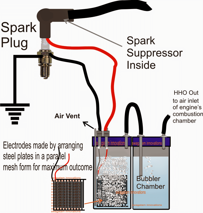
An easy to understand set up for generating "on demand HHO gas" can be witnessed in the above diagram.

The electrodes are made out of  good quality stainless steel pates which are appropriately arranged in a mesh like formation through a face to face intersection but without touching each other.

Using Baking Soda to Increase Efficiency

A little baking soda is added in the water for speeding up the electrolysis process and assisting the electrons to flow with greater efficiency.

In the left container we can see an air vent pipe, this is introduced to allow air to pass inside the vessel as the water is electrolyzed into HHO gas. This air vent pipe prevents vacuum formation in the vessel while the electrolysis is in process.

Since the input high voltage is derived from the motorcycle's CDI coil or the spark plug, we can assume it to be in sync with the engines RPM and in accordance with the speed of the vehicle. Therefore the chance of inducing a disproportionate amount of HHO inside the combustion chamber is automatically controlled, making the procedures much safer and healthier for the vehicle's engine.

The HHO gas output from the bubbler chamber is directly integrated with the air intake passage of the motorcycle's combustion chamber.

Once the above set up is installed and initiated, an immediate improvement in the performance of the motorcycle's engine could be expected and a drastic reduction in the consumption of the primary fuel could be witnessed.

WARNING: THE PROPOSED CONSTRUCTION GUIDE OF HHO GAS IN MOTORCYCLE FOR IMPROVING ITS EFFICIENCY HAS NOT YET BEEN TESTED BY THE AUTHOR PRACTICALLY, EXTREME CAUTION AND CARE MUST BE EXERCISED WHILE TRYING THE EXPLAINED THEORY. THE AUTHOR CANNOT BE HELD RESPONSIBLE IN AN EVENT OF AN ACCIDENT OR A FAILURE OF THE PROJECT WHILE CARRYING OUT THE EXPERIMENT.
You'll also like:

  • oilburnercontrollercircuitOil Burner Button Start Ignition Circuit
  • enhanced CDIElectronic 12V DC Capacitive Discharge Ignition (CDI) Circuits
  • carRegenerative Braking System in Automobiles (Circuit Diagram)
  • car led bulb circuitHow to Make Car LED Bulb Circuit

Filed Under: Automobile Electronics, Energy from Magnets and Earth Tagged With: Automobiles, better, Cell, Efficiency, Fuel, HHO

About Swagatam

I am an electronics engineer and doing practical hands-on work from more than 15 years now. Building real circuits, testing them and also making PCB layouts by myself. I really love doing all these things like inventing something new, designing electronics and also helping other people like hobby guys who want to make their own cool circuits at home.

And that is the main reason why I started this website homemade-circuits.com, to share different types of circuit ideas..

If you are having any kind of doubt or question related to circuits then just write down your question in the comment box below, I am like always checking, so I guarantee I will reply you for sure!


Previous Post: « PWM Solar Battery Charger Circuit
Next Post: How to Generate Electricity from a Pendulum »

Reader Interactions

Questions & Answers

Total Posts: 177
Newest Oldest
Mike Garrard
July 14, 2026 • 1 month ago #209926

Oh good grief.
1) You are not ‘creating’ energy, you are converting energy. HHO ‘gas’ does not exist. Look at the spout when you next boil water: you can’t see the vaporised water just about the spout: it must condense before it becomes visible. When you electrolyse water, you get O2 at one electrode and H2 at the other. These two mix to form an explosive gas with a very low ignition energy: 2mJ will do. In the proposal, these are inside a sealed container, so if they do explode then the outcome will likely be complete destruction of your kit.
2) Burning gasoline released about 47MJ per kg. Combustion inside your engine is about 98% efficient: this is required to meet emissions standards as the controlled emissions are either incomplete combustion (HC & NMOG) or excess combustion (NOx).
3) There is no grand conspiracy of OEMs or ‘big oil’ working to undermine the efficiency of your engine/vehicle. I work for an OEM. Every few years I get an unsolicited proposal that, in a physics defying way, will significantly improve the gas mileage. I’ve tested a few on engine dyno (the gold standard of efficiency testing) and NONE of them worked: not the magnets around the fuel line; not the alloy of antimony and tin pellets in the fuel tank; not the vortex exhaust, or a vortex in-front of the MAF.
4) Commercial electrolysers already exist to create small quantities of Hydrogen. However, your problems will start there: in what are you going to store your Hydrogen? Hydrogen vehicles use a tank pressure of 70MPascals (cars) or 35MPascals (commercial vehicles). Note that you as a human have no detection mechanism for a hydrogen leak: it has no smell, and burns with a colourless flame. The first you know that a) you have a leak and b) it’s on fire, will be when your clothes/hair/vehicle start burning. Don’t Jerry-Rig this: you are literally playing with fire. Swagatam can confirm email is at an OEM.

Reply
eq
June 27, 2025 • 1 year ago #182948

Hello my Friend, hope you are well!

Quick question for you, if I’m trying to put a capacitor across the output of my HHO cell to smooth out the current, what size capacitor/supercapacitor do I need?

My cell is powered by a 12v car battery and the battery is being charged by a 12v 30a charger connected to 220v outlet at home.

Reply
SwagatamAdmin
June 27, 2025 • 1 year ago #182969

Hi eq,
the capacitor can be any large value capacitor, the bigger the better, like a 2200uF, or 4700uF, or even a 6800uF etc.

Reply
eq
June 27, 2025 • 1 year ago #182991

thank you!

Reply
eq
May 25, 2025 • 1 year ago #178299

first of all I just want to say ‘Thanks’.
you answered some questions for me like 5 YEARS ago.

HHO question for you, slightly off topic*
I’m following an online plan to build a simple 12v Hho cell but it requires 20a. I can’t get 20a since it’s a 6.5 Chinese generator and doesn’t have a battery as you know(& charging coil only makes like 3a I think)
how can I over come this on a small budget?

the idea I have is too get a 20a-30a 12v battery charger and run the cell from this from the output side of the generator, is this even possible?

please let me know what you think, thanks!

Reply
SwagatamAdmin
May 25, 2025 • 1 year ago #178309

You are most welcome eq!
using 12V 20 amps to generate HHO gas means involving 20 * 12 = 240 watts of power. In that case the generated HHo gas should be able to power a motor rated to handle more than 300 watts, only then it will be a beneficial deal, otherwise it will be a waste of energy and efforts, right? or maybe I did not understand your requirement correctly…please let me know.

Reply
eq
May 25, 2025 • 1 year ago #178321

yes, correct, it’s just a basic 1500Watt generator.
so if I understand you correctly, you are saying about 240 watts will go towards powering the HHO and the rest of 1260 will be available to power other devices?

so in your opinion is it worth it or is this better on a large generator?(if so what size generator do you recommend?)

do you also recommend this approach(using the generator output to power the cell) or would you do it differently if it was you?

Reply
SwagatamAdmin
May 26, 2025 • 1 year ago #178407

Sorry, I don’t think I understood your application correctly.
Can you please explain the flow diagram or the flowchart… what is the purpose of the HHO gas here.
You said it was a 6.5 Chinese generator, then what is this basic 1500Watt generator?

Reply
eq
June 3, 2025 • 1 year ago #179648

hello, sorry for the misunderstanding.
What I was trying to say is that it’s a 1500watt generator and like you mentioned it needs about 240 watts to power the hho. so I’m left with about 1260 watts to power other devices.

What I’m trying to understand is how to efficiently power the hho cell because the generator DOESN’T HAVE BATTERY where I can connect the hho cell, so I have to use a different source(the idea I have is to connect the hho once the generator is running: connect it to the 220v outlet and the use a 20a 12v battery charger to run the hho cell)

So I am interested in your opinion, whether this is the best method to power the hho cell(if not, what would you recommend)?

Reply
SwagatamAdmin
June 4, 2025 • 1 year ago #179719

What is the voltage output from the generator? If you want extreme efficiency then you can consider converting the generator output to a 3V DC, using a buck converter, and then use this DC for the electrolysis of water with a drop of H2SO4 in it, to generate high amounts of HHO with high efficiency.

Reply
eq
June 4, 2025 • 1 year ago #179769

im new to all this, can you please clarify

so based on the instructions for the cell to work efficiently it says:
I need 12v. 20a
the device has 6 cells
which is about 2v per cell(you need 1.24v per cell for maximum efficiency)

so will the 3v buck converter be enough since I require about 12v total?

what is the reason for the buck converter?

Reply
eq
June 4, 2025 • 1 year ago #179780

my generator is 1500watts
and has 220v outlet

Reply
SwagatamAdmin
June 4, 2025 • 1 year ago #179787

Sure, let me check, I will try to design it soon and let you know!

Reply
eq
June 6, 2025 • 1 year ago #180086

thanks for all your assistance Sir!

Reply
SwagatamAdmin
June 7, 2025 • 1 year ago #180150

you are welcome eq…

Reply
eq
June 5, 2025 • 1 year ago #179897

wow I just saw the circuit you designed for me.
Thank you Sir, you’ve true gone Above and Beyond, can’t thank you enough.
I’ll find someone who understands circuits to look over it for me!

While on the subject of circuits, what do you think of this one
original66e148a108fcd9.29944686

this one is simple enough for even me to understand it without any elect engineering background.

my question for you is, if this was done with two 72v batteries, what can you use as the one way diode?

Reply
SwagatamAdmin
June 6, 2025 • 1 year ago #179996

You are most welcome eq, for the diode in the attached diagram, the diode will depend on the switching current and frequency. If the current is say 5 amps, and switching frequency above 1kHz then you can use any fast recovery diode rated at 5 amp, and so on. If the frequency is lower, then the diode can be any rectifier diode like 6A4…

Reply
eq
June 5, 2025 • 1 year ago #179869

sounds great, thank you!

Reply
SwagatamAdmin
June 5, 2025 • 1 year ago #179890

Ok, here’s the circuit you can build for getting 12V from 220V for your HHO cell. Make sure to use appropriately dimensioned super enameled litz wire for the inductor, wound over a ferrite ring core.
buck converter

Reply
SwagatamAdmin
June 4, 2025 • 1 year ago #179778

Actually I was referring to 3V per cell, but no issues, 2V is even better, so yes 12V 20 amp is good enough for your 6 series cells application.
Let me know about the input voltage specifications from the generator, then I may try to figure out the buck converter design…

Reply
eq
June 4, 2025 • 1 year ago #179766

this is the hho cell I’m trying to use
https://www.homemade-circuits.com/wp-content/uploads/2025/06/HHO-pdf.pdf
(as you can see it requires 12v 20a to be most efficient without getting hot)

this is the type of generator I have
generator

Reply
SwagatamAdmin
June 4, 2025 • 1 year ago #179786

OK, thanks, Got it!!

Reply
Dalibor
December 14, 2024 • 2 years ago #167315

Hello, your original design for this topic is removed by you for security reasons, but topic is the same, question is in order to produce hho with HV in pure water, by dumping HV in KV but amps must be restricted in miliamps, exactly below 100ma?

Reply
SwagatamAdmin
December 15, 2024 • 2 years ago #167331

Hi, thanks for your suggestions…Yes, the current will be low and much below 100mA for the above project…

Reply
Dalibor
December 15, 2024 • 2 years ago #167375

I’m more interested in you original cdi circuit, and several other projects, one of them is Meyer brushed rewinded alternator… To keep it short, plan is to build-replace alternator stator windings with 4x CDI coils around rotor to simulate 4x phases with HV impulse.. For now
i know Meyer dereulated multi phases alternator work but not enough gas to start engine like him, he probably rewinded stator to 9 phases with thin vire to get HV, Cdi would be simpler to build and achieve same thing.

Reply
SwagatamAdmin
December 16, 2024 • 2 years ago #167394

The basic CDI circuit can be found in the following links:
https://www.homemade-circuits.com/how-to-make-capacitive-discharge/
https://www.homemade-circuits.com/make-this-enhanced-capacitive-discharge/
I have not yet studied the Meyer alternator, so unable to provide my opinion on this.
I hope you succeed with this project.
Please do keep us updated with the results.

Reply
Safak TASKIN
July 5, 2024 • 2 years ago #153556

Additionally; I recommend you to examine the “Voltage Multiplier” circuits with only diodes and capacitors from 220Vac. It will be easier and more practical to obtain High voltage DC by adding it to the output.
Stay happy.
Şafak TAŞKIN from TURKEY.

Reply
SwagatamAdmin
July 6, 2024 • 2 years ago #153638

Thank you for your interesting feedback. yes, that’s definitely worth trying.
I appreciate the idea.

Reply
Safak TASKIN
July 5, 2024 • 2 years ago #153548

Greetings. It was a project I did about 20-25 years ago. Regarding high voltage, I definitely agree with you, as is my experience. Best Regards.
Safak TASKIN from TURKEY.

Reply
Tunji Akande
April 15, 2024 • 2 years ago #151581

Good morning sir, How are you doing today sir, sorry to disturb you again sir, Sir I construct hho cell using aluminium pipe with each having a distance of at least 1mm apart, is the distance apart OK?, another thing the amount of heat been dissipated is a lot sir

Reply
SwagatamAdmin
April 15, 2024 • 2 years ago #151584

Hi Tunji,
what DC voltage are you using, and are you using any chemical in the water? If the DC is 3V and above and there is no chemical used, then 1 mm distance is fine.
If you are using a chemical like sulphuric acid, or similar then you can try wider distances also.

Reply
Tunji Akande
August 16, 2024 • 2 years ago #158162

Hi sir, please I need your advice on this Dc generator, I need to know if I can use it for the experiment above, and what should be the distance apart for the Aluminum rod that I’m using

https://www.konga.com/product/switching-power-supply-ac-dc-power-supply-5v-40a-200w-6079466

Or Aliexpress
https://www.aliexpress.com/i/2251832698536301.html?gatewayAdapt=4itemAdapt

Or which power supply can you recommend, and also if 12v 1A transformer to Dc, can be made somehow efficient

Reply
SwagatamAdmin
August 17, 2024 • 2 years ago #158199

Hi Tunji,
Yes, you can use those power supplies for generating HHO gas.
Alternatively you can simply use a 12V 1 amp AC to DC power supply for generating HHO gas.
For 5V DC, the distance between the electrodes inside water can be around 1 inch.
For 12V it could be anywhere between 2 inches and 1 inches.
The closer the better.
The cross section area of the electrodes also matters, bigger cross section will produce higher amounts of HHO.

Reply
Tunji Akande
April 15, 2024 • 2 years ago #151591

I’m using 220V Dc, converted directly from AC, I’m not using any electrolyte.

Reply
SwagatamAdmin
April 16, 2024 • 2 years ago #151604

In that case you can keep 2 inches distance between the probes.
Please remember that using 220V can be fatal if not handled carefully and with necessary precautions.
You are doing it at your own risk.

Reply
Tunji Akande
April 16, 2024 • 2 years ago #151605

OK, thank you so much sir, I really appreciate it.

Reply
SwagatamAdmin
April 16, 2024 • 2 years ago #151606

You are welcome Tunji…

Reply
Tunji Akande
March 4, 2024 • 2 years ago #149716

Hi, I saw a video on YouTube, where someone is using Dc to Dc boost converter for Hho gas generator, with potassium hydroxide or sodium hydroxide in the water.
Sir with this type of implemention will the hho gas be efficient? If what modification can be done to increase it production?

Reply
SwagatamAdmin
March 4, 2024 • 2 years ago #149726

Boost converter will work if it has high current otherwise it won’t be efficient.
You can try something like this:
https://www.homemade-circuits.com/how-to-generate-pure-oxygen-and/

Reply
Tunji Akande
March 4, 2024 • 2 years ago #149733

Wow, thank you so much sir for that quick reply, though I still have one more question sir, can I 3v to 6v ==> 10kv to 20kv power module, will it work?, is it effective? Or just a waste power? And which is preferable Sodium hydroxide or Potassium hydroxide as a solvent in water?

Reply
SwagatamAdmin
March 4, 2024 • 2 years ago #149737

Thank you Tunji, If you are using a catalyst then you just need 3v for efficient generation of hho, rest everything is waste of power.
A drop of sulphuric acid is actually the best catalyst for fast electrolysis of water, however out of those two, sodium hydroxide is the preferable one.

Reply
sean
January 12, 2026 • 7 months ago #199011

if im already using KOH on my drycell hho setup, does adding sulfuric acid make it more efficient?
my system draw around 3.4a @ 12v

Reply
SwagatamAdmin
January 12, 2026 • 7 months ago #199019

If you are already using KOH in a dry cell HHO setup then adding sulfuric acid will not make it more efficient, because KOH is alkaline and sulfuric acid is acidic…. so when both mix they neutralize each other and form potassium sulfate and water, now this reduces OH− ions which are actually needed for proper electrolysis. So heat increases, gas output becomes unstable, and also efficiency goes down instead of up, hence a dry cell must be either alkaline with KOH or acidic, but never both mixed together.

Reply
Tunji Akande
March 25, 2024 • 2 years ago #150786

Sorry, to disturb you again sir, I wanted to use multiple 3.7v lithium batteries, how should I connect them in series or in parallel for efficient Hho generation, thank you sir.

Reply
SwagatamAdmin
March 25, 2024 • 2 years ago #150808

You can connect them in parallel.

Reply
Tunji Akande
March 25, 2024 • 2 years ago #150825

Thank you so much sir

Reply
SwagatamAdmin
March 25, 2024 • 2 years ago #150826

You are welcome Tunji…

Reply
Tunji Akande
March 4, 2024 • 2 years ago #149739

OK thank you so much sir

Reply
dare
January 7, 2024 • 3 years ago #148433

So spark plug is for gating?

Reply
Richard Chapman
April 10, 2023 • 3 years ago #141701

Couldn’t you do the same with just a coil pack? Some go from 20000v to up to 50000v. I know I am making a full inclosed system with that.

Reply
Anthony
January 11, 2023 • 4 years ago #138800

Hello, I understand everything here except one small detail, how do you physically connect the power and ground wires to the spark plug/resistor cap? Thanks.

Reply
SwagatamAdmin
January 12, 2023 • 4 years ago #138806

Spark plug body will be already connected with the vehicle body, no need to connect it physically. The power comes from the ignition coil to the spark plug.

Reply
Alex
November 6, 2022 • 4 years ago #134440

Thank you for your sharing your knowledge. I’m interesting with your HHO driver but I’m just a beginner. So please can you help me with my 13 plat dry cell hho generator. How I can install it in my car? How I can make PWM to adjuste amps for hho. Thank you for your cooperation and help.

Reply
SwagatamAdmin
November 6, 2022 • 4 years ago #134455

Hi, I appreciate your interest, however if you are a beginner then this circuit may not be recommended for you. The above HHO cell experiment is recommended only for the experts or must be done under the supervision of a qualified and expert automotive/electronic engineer.

Reply
Alex
November 6, 2022 • 4 years ago #134485

First thank you for your reply. Please Don’t worry I have done a lot of things. And I’m willing to learn every day new things, no body born with full of knowledge we all born to learn. So please help me I know you could help me. Thank you again.

Reply
SwagatamAdmin
November 7, 2022 • 4 years ago #134494

OK, in that case you can go ahead with this project. However you would still need the help of a qualified automotive engineer to learn how to implement it in an automobile. I won’t be able to help with the automotive implementation. I can only help you with the building of the circuit and the PWM

Reply
Alex
November 7, 2022 • 4 years ago #134498

I’m glad to here this from you. Please send me everything you could so I can start to build the PWM or try the car’s spark plug. I have bought some PWM speed controller but it’s getting hotter not even reach to 15A. So please what can I do?

Reply
SwagatamAdmin
November 7, 2022 • 4 years ago #134503

No problem! You can build the following HHO PWM controller circuit and use it to build your HHO generator circuit. Make sure that the electrodes never touch each other inside water, otherwise the transistor will burn instantly. Also, you can try adding a few drops of H2SO4 or sulfuric acid in the water to speed up the HHO generation process.
555 pwm for hho cell generator

Reply
Constantin
August 31, 2022 • 4 years ago #132799

Hi, the link to the previous post is not working, please direct me to the CDI coil circuit for HHO. Thanks

Reply
SwagatamAdmin
August 31, 2022 • 4 years ago #132805

Hi, unfortunately, I had to delete the post because making HHO at home can be very dangerous and strictly not recommended.
For the CDI coil circuit you can refer to the following post:

https://www.homemade-circuits.com/make-this-enhanced-capacitive-discharge/

Reply
Alex
June 17, 2022 • 4 years ago #127030

Dear Swagatam, thank you very much for sharing with the world your knowledge, much appreciated!
I would like to implement this setup with an OHV driven electrical generator, where the spark cable at the coil is not detachable. Can you or some fellow readers here suggest how to create the suggested parallel derivation, so I can have the spark and HHO cell both poeered by/from this single cable?

Thank you very much in advance!

Reply
SwagatamAdmin
June 17, 2022 • 4 years ago #127129

Thank you Alex, for your valuable feedback. I appreciate it.
You can extract the high voltage from the high tension wire clip of the ignition coil which is fixed at the neck of the spark plug. That is probably the only place from where you can extract the high voltage.

Reply
Thai Bryan
June 13, 2022 • 4 years ago #125532

I am building a 49 plate dry cell set up for my 6.0l truck engine. I was wondering if I could use my existing air conditioner circuit wiring to power the unit or would additional breakers and or transformers be needed. The plan is to unplug at the ac condenser and wire in with new disconnect plugs utilizing the existing ac circuitry.

Reply
SwagatamAdmin
June 13, 2022 • 4 years ago #125537

Hi, Sorry I have no idea about the air conditioner circuit, so it can be difficult for me to comment on this.

Reply
Arno
April 19, 2022 • 4 years ago #119129

Resistor is Royal 1693, 10KJM5w ceramic ?

Reply
SwagatamAdmin
April 19, 2022 • 4 years ago #119158

You can buy any 10K 5 watt resistor, the one which you showed me earlier will work nicely. However this resistor is not a confirmed value….if this does not work then you may have to buy some other lower value until the bubbling through the electrolytic is just prefect

Reply
Arno
April 20, 2022 • 4 years ago #119192

Sorry for stupid questions. Talking like 5k 3 w as next level resistor? Would fine tunng work with little electrolyte NaOH if weak? Just need to understand if the same influence electrolyte jas driven by amp as V. The more electrolytes the more gas but that draws amp and heat.

Reply
SwagatamAdmin
April 20, 2022 • 4 years ago #119233

You can use H2SO4 for enhancing the effect but I won’t recommend that since the supply input is too high, and adding any chemical may cause explosion in the electrolyte. Do not use any external chemicals.

Reply
Arno
April 19, 2022 • 4 years ago #119128

You must excuse me looking at the options, I am in South Africa. Some things are lmited and then some places want your arm and leg order. Buying online here is a nightmare by its srlf. Our postal services and public transport have come to a standstill for corruption and bankruptcy. Petrol/gas cost is another Govtax and public abuse. Getting things done here affordable is a challenge with distances.

Reply
SwagatamAdmin
April 19, 2022 • 4 years ago #119156

OK I understand, no problem.

Reply
Arno
April 19, 2022 • 4 years ago #119126

Thanks on that feed back, just considering your diagram for clarity in your suggestions, the fuse will be going on the red wire from the HHO generator unit to the spark plug wire. There will also be the resistor 10k-5w. The fuse will then be between the resistor and HHO unit.? Will there be a problem using a ceramic 10k- 5w resistor (you suggested the wound type) I only found ceramic at our suppliers. The secondary fuse on the coil would be where? Wire to plug or power feed to the coil? To get back to previous suggestion on switch from battery power source to coil source

In the previous discussion on the automatic relay switch from battery to coil. Those box switches are used in cars but determine 12V. Would that work to switch from battery to coil plug wire (always refer as coil being the source)in some Amp variation or do we we look at something different, considering volts. Rally appreciate you insight to the solution.( are there a basic component already outhere like car relay switch or does need a new combination of components.
See https://duckduckgo.com/?q=Relay%20switch%20used%20in%20car&ko=-1&iax=images&ia=images

Reply
SwagatamAdmin
April 20, 2022 • 4 years ago #119232

You are correct regarding the position of the fuse, however if a 10K resistor is being used a fuse may become meaningless, because the 10K will be enough to handle the short circuit and prevent burning of the wires. A ceramic resistor may also work, just check whether the resistor is heating up or not….if it heats up then ceramic will not work.

Any 5 pin 12V car relay will work which are shown in the image sent by you.

Reply
Arno
April 18, 2022 • 4 years ago #118933

Considering there is a 16amp fuse used with a battery unit, safety amp. Is similar safe guard required with coil solution?

Reply
SwagatamAdmin
April 18, 2022 • 4 years ago #118967

You can put one fuse for the coil and the electrolysis circuit, it is never a bad idea.

Reply
Arno
April 16, 2022 • 4 years ago #118768

Through many discussion you have mentioned so many surpressors and resistors?/Another point as very stupid question after google search to confirm and be sure. “The resistance can be a 10K 5 watt wire, wound resistor.” This is a thick 10k5w cable wound to coil?
Or specific 10k5w resistor you buy thats cable wound (I believe is correct)

Reply
SwagatamAdmin
April 16, 2022 • 4 years ago #118792

Yes that’s correct.

Reply
Arno
April 16, 2022 • 4 years ago #118769

Ok, got the wire wound resistor
wire wound resistor
Not to assume but you suggested this in regards to the whole chat considering my HHO design also plates 3 mm apart?

Reply
SwagatamAdmin
April 17, 2022 • 4 years ago #118888

OK will do….but plate distance will need to be adjusted with practical experimentation only…

Reply
Arno
April 16, 2022 • 4 years ago #118710

Thanks for your responce. Just to make sure we are on the same page, please bare with me. The red wire,(before spark plug, no other place can attach to coil) you refer to your image? Then there is a suppressor in series between the HHo system connected. THE PPC(105/400v PPC) is a suppressor additional or the suppressor referred to(should be sufficient for bike or car you also referred to the 3 mm carbon rod in a chat sounded to be for bike). The suppressor if only one used can be increased. 105 can < to higher. For example, what would be the next one up? I am pure novis at this and would hate to waste your time and really appreciate it. Thanks

Reply
SwagatamAdmin
April 16, 2022 • 4 years ago #118746

The simple idea to suppress the high voltage/current into the electrolysis unit would be to connect series resistor with the red wire that goes into the water. The resistance can be a 10K 5 watt wire wound resistor. !05 capacitor or any other capacitor cannot be used as a suppressor due to their low voltage rating. The 105 capacitor is supposed to be inside the CDI unit which generates the capacitive discharge into the ignition coil.

Reply
Arno
April 16, 2022 • 4 years ago #118761

Thanks again for your patients. All info with comments got confusing at first. The 105 refered to the PPC (105/400v) suppressor, not the capacitor, sorry you have much more info in your head. Having reread your explanation without comments brought a bit of clarity. In my mind came up last concern of this as a fully working model. Power draw from the coil is a great concept but concern drawing from the coil rather than from the battery came to mind. Coil active to HHO generator with bike ONLY when the bike is running but how does it start with fuel and gas in the carburettor. BatTERY starts Hho before ignition so we have generated H gas to carborator(which would now also be preset for a saving balance) to keep balance of H and feul to start bike. Coil will have no H to carborabtor on the start. As I believe the carb get set for balance of feul and H mixture. So conclusion needs to bridge this delema. Will solution be to have a switch from baterry power to coil when you start bike? Do you envisage this delema or did I miss something.

Reply
SwagatamAdmin
April 16, 2022 • 4 years ago #118762

Thanks, I appreciate your question, however I am not an expert with automobile engine mechanism, so I cannot suggest regarding how the HHO is supposed to react or work with the engine of the bike….this will need to be confirmed from an qualified automobile engineer.

Reply
Arno
April 16, 2022 • 4 years ago #118770

Having researched around HHO, I explained you the concept and realise your skill and lack. The solution is electrically connected to swith from one to another to bridge a point from when H gas is required that AC or DC needs supply to ignition of its use for the continium of the coil keeping H gas generation. This is purely an electrical sulution posisibly by switch. So your electical opinion on this as an exercise or other solution than a swith. Is there complications with a sqith and possibly what would such a diagram work for this excise considering the explanation of working. Appreciating you input!

Reply
Arno
April 16, 2022 • 4 years ago #118822

Haha, sorry yes missed spell!
The solution is electrical. To bridge the problem. So at the point where the system can switch over from generating H gas required from required AC from the battery to needing H gas supply from coil. This could be achieved by using a switch in circuitry. Manual is easy. What about an automatic switch over. So when coil power kicks in HHO CELL swith overdrawing power from the coil. Could this be a challenge for you? Think it is a great solution. A Diagram of the components of this could be great!

Appreciating your input on concerns and the real impact on the different components. Amp draw enough gas for the battery to start the bike then riding replenish battery when HHO UNIT running from the coil.

Hope it’s clearer. Thank you so much for your patience and response

Reply
SwagatamAdmin
April 17, 2022 • 4 years ago #118885

OK no problem, however, The HHO gas is only supposed to be an additional support for the existing fuel of the vehicle, the HHO alone cannot be used to power the engine.
So initially the engine will be started with petrol or diesel, and once the ignition coil is started then HHO can be released into the combustion chamber as an extra support to the petrol or diesel and for enhanced engine combustion with little petrol or diesel.

Reply
Arno
April 17, 2022 • 4 years ago #118911

You correct! My concern is that carburettor adjustment with a good H gas flow settings may influence the bike difficult to start. Diverse bikes would then. have a working opportunity when you set a lean system. As the carburettor settings change with totally different settings to reduce fuel with more air H mix. This only way to maximise saving otherwise you waste fuel in combustion that H accommodation wast ob both feul elements.

There are many voices out there in the solution while combined wisdom gives a better solution for us all. Your suggestion from the HHO cell system is the best contribution to improve them while working in my opinion for bikes. The biggest problem is battery drain and then to improve the overall HHO combination percentage will theoretically be possible for larger CC and possibly full H IN SMALL.CC. If we can keep heat in the HHO cell low enough it will be a great solution with that switch which the suppressor would be included on a little board.

Considering taking it a strep further PWM (control amps keeping heat control)can be added for control but With that coil supply with a suppressor? Will it work on that coil supply considering amps or volts? What amp PWM would work considering amps without going too high or low? Your insight into electronics is of great value working in these diverse knowledge fields. Thanks for your responses, really appreciate it. I am sure many others coming to this page.

Reply
SwagatamAdmin
April 17, 2022 • 4 years ago #118921

Thank you for your detailed explanation, I appreciate it! Unfortunately PWM may not be possible because here we are dealing with 20000 volts, only a resistor will be acceptable in this situation to control the excess current to the electrodes.

Reply
SwagatamAdmin
April 16, 2022 • 4 years ago #118793

Sorry, I cannot understand your English translation.

Reply
Arno
April 15, 2022 • 4 years ago #118645

Hi great idea! Been looking at solution to save battery 12v battery on bike, HHO draw 3.8 A. Wondering if bike alenator could replenish that on battery and not go flat? Opinion here?

Considering your solution of drawing from coil.
Placing suppressor in series to HHO system and you mentioned cathode and anode plate appart 2/inches. Considering my HHO system design with plates 3mm appart WITH ROD IN TUBE IDEA. ( a 2nd design, There is points of isolation between of 1mm at some points but plates +NN-NN+ all in water) Would the suppressor strenght help with this spacing. The voltage and jump. Would I use 2 in series, what’s your suggestion like the PPC 105 be sufficient? THEN TOTALLY AVOID 2 nd design, considering volt jump or spark? I really, appreciate your insights

Reply
SwagatamAdmin
April 15, 2022 • 4 years ago #118675

Hi, thanks, glad you liked the concept!

I think the suppressor should be actually in series with the electrolysis supply (red wire) instead of the high tension supply. This will ensure two things, current consumption will be low which will save power, and this will also stop the arc from jumping across the electrodes. However, the electrode distance should be a mater of experimentation, and it should so adjusted that the spark can never jump across the electrodes, or alternatively the suppressor value could be increased for achieving the same. 105 value should not be changed or reduced otherwise that could affect the sparking in the spark plug

Reply
Arno
April 15, 2022 • 4 years ago #118646

Add info, bike is 250 skygo

Reply
Wayne Crowley
September 1, 2021 • 5 years ago #96101

Hello from Cape Town, South Africa.
The idea of diverting current from the spark plug concerns me as I’d be wary of misfires resulting.
A possible solution may be to invest in a cheat HT coil from a scooter or similar. Wire it in parallel to the engines HT coil then do what you like with a isolated ht spark.
As my bike was stolen last Monday (goodbye test bed) have not tried this but don’t see why it wont work.

Reply
SwagatamAdmin
September 1, 2021 • 5 years ago #96109

Hi, The idea here is to use the excess energy from the spark and use it for the electrolysis. There won’t be any misfires because the spark gap is very small and the voltage from the ignition coil is too high for the small gap, so even with a little reduced current the sparking won’t be affected.

Using an external ignition coil might not help the purpose since it would consume extra power from the alternator for the electrolysis.

Reply
Tony
September 19, 2021 • 5 years ago #97996

Nice idea, i connected the wires to the spark plug but the engine wound not start, when i disconnected the wires the engine started,i did exacta as the diagram.
Thanks for the nice idea, thumps up from me!!!

Reply
SwagatamAdmin
September 20, 2021 • 5 years ago #98038

Please connect a 1K 1 watt resistor in series with the HHO supply and check again, and make sure the HHO water probes are at least 3 inches apart in water, and do not put any external chemicals in water. If 1K doesn’t work, try higher values!

Reply
JP
April 27, 2021 • 5 years ago #88787

Several questions –

First, how long will the baking soda last?

Second, how would you keep the water from freezing in the winter?

Third, why would you run the air through the air intake instead of off the vacuum of the motor?

Fourth, ideally this would start off HHO but won’t it need to start off fossil fuels and then flip over?

Fifth – what is the ideal spacing between plates? Or is it better to try and locate woven stainless or perhaps stainless steel wool?

Lastly – Would running a cap in place of a battery work? I understand about caps and batteries, but it would make sense for space reasons to start the process off a cap before the vehicle starts.

Reply
SwagatamAdmin
April 27, 2021 • 5 years ago #88793

I don’t using any catalyst in water, just simple tap water will do.
The concept might not work in countries with freezing temperatures. Or perhaps the rise in temperature due to electrolysis could convert the ice into water.
I did not properly understand your 4rth point.
The spacing can be around 2 inches apart.
If there’s no battery then it can be started with an alternator, but capacitor might not work…

Reply
View Older Comments

Need Help? Please Leave a Comment! We value your input—Kindly keep it relevant to the above topic! Cancel reply

Your email address will not be published. Required fields are marked *

Primary Sidebar


Categories

  • Arduino Projects (95)
  • Audio and Amplifier Projects (134)
  • Automation Projects (18)
  • Automobile Electronics (104)
  • Battery Charger Circuits (90)
  • Datasheets and Components (109)
  • Electronics Theory (150)
  • Energy from Magnets and Earth (41)
  • Games and Sports Projects (11)
  • Grid and 3-Phase (20)
  • Health related Projects (27)
  • Home Electrical Circuits (13)
  • Indicator Circuits (16)
  • Inverter Circuits (100)
  • Lamps and Lights (163)
  • Meters and Testers (72)
  • Mini Projects (28)
  • Motor Controller (68)
  • Oscillator Circuits (30)
  • Pets and Pests (15)
  • Power Supply Circuits (91)
  • Remote Control Circuits (50)
  • Security and Alarm (65)
  • Sensors and Detectors (107)
  • SMPS and Converters (46)
  • Solar Controller Circuits (62)
  • Temperature Controllers (44)
  • Timer and Delay Relay (50)
  • Voltage Control and Protection (44)
  • Water Controller (37)
  • Wireless Circuits (31)


Circuit Simulator

circuit simulator image


Subscribe to get New Circuits in your Email


Other Links

  • Privacy Policy
  • Cookie Policy
  • Disclaimer
  • Copyright
  • Videos
  • Sitemap

People also Search

555 Circuits | 741 Circuits | LM324 Circuits | LM338 Circuits | 4017 Circuits | Ultrasonic Projects | SMPS Projects | Christmas Projects | MOSFETs | Radio Circuits | Laser Circuits | PIR Projects |


Recent Comments

  • Swagatam on 4 Simple Battery Desulfator Circuits Explored
  • Swagatam on Electronic Circuit Projects, Tutorials, and Practical Engineering Solutions
  • AntoDas8 on 4 Simple Battery Desulfator Circuits Explored
  • Swagatam on 50 Watt Sine Wave UPS Circuit
  • Tom Sendelbeck on Electronic Circuit Projects, Tutorials, and Practical Engineering Solutions

Social Profiles

  • Twitter
  • YouTube
  • Instagram
  • Pinterest
  • My Facebook-Page
  • Stack Exchange
  • Linkedin

© 2026 · Swagatam Innovations