The first design below shows a simple workbench setup for testing all types CDI circuits. It uses a capacitive discharge ignition circuit along with a CDI coil to implement the testing procedure.
Audio/Video Representation
The circuit does not require any separate oscillator, rather the 100Hz from the bridge rectifier itself works like a pulsed trigger for the CDI trigger input, for generating the sparks at 100Hz fast rate.

Purpose Of The Setup
We are making this whole setup so that we can test one CDI coil ignition circuit right on the table, without needing any bike engine or alternator. We want to see that spark properly. So we use some small transformers and one bridge rectifier that will give us the same kind of high voltage like bike alternator but with very low current so that it stays safe for testing.
Basic Working Idea
We know that in an actual motorcycle, that alternator coil gives high voltage AC around 100V to 250V whenever engine keeps rotating. That AC goes inside CDI circuit where it charges one capacitor. Then the SCR gets triggered from one pickup coil pulse and it suddenly discharges that capacitor into ignition coil, and that makes the high voltage spark.
So here in this test circuit, we are trying to make that same kind of AC using two small 12V-0-12V transformers which are connected back-to-back. This gives us isolated 220V low current AC that behaves like the alternator supply.
Transformer Connection
You can see two small transformers on the right side each rated 12V-0-12V 500mA.
Now we take the first transformer and feed 220V AC mains to its primary. So its secondary gives about 12V AC.
Then we take the second transformer and we connect its 12V winding with the 12V winding of the first transformer.
So now the primary of the second transformer starts giving again around 220V AC but this time with very low current because the power is going through two transformer windings.
So we get safe, isolated and low current 220V AC output which acts like the alternator AC for the CDI circuit.
Bridge Rectifier For Trigger Pulses
Now the important part — the bridge rectifier made from 1N4007 diodes....it is connected to the 12V AC secondary of the left transformer. So this bridge rectifier only converts the 12V AC into 12V pulsed DC.
Because 12V AC has 50Hz frequency, so after full wave rectification it becomes pulsed DC at 100Hz. That means we get two DC pulses for each AC cycle. So this pulsed DC is applied to the trigger input section of the CDI circuit.
Now every time this pulsed DC hits the SCR gate input, then the SCR turns ON for a moment and discharges the main capacitor C4 through the ignition coil. So the ignition coil keeps firing sparks one after another at the same 100Hz rate.
What Happens Inside CDI
Inside the CDI circuit, the capacitor C4 gets charged through the 220V low current AC from the transformer secondary. That high voltage keeps the capacitor ready all the time.
At the same time, the pulsed DC from the bridge rectifier keeps triggering the SCR gate at 100 times per second.
So each time the SCR gets pulse, then it fires, dumps the capacitor charge into the ignition coil and creates a spark at the plug. Since this happens 100 times per second, so you get a rapid series of sparks at around 100Hz rate.
Spark Observation
You will see that ignition coil output wire or spark plug will keep sparking continuously at high rate. The spark will look like a fast chain of sparks because the CDI circuit is getting triggered continuously by that 100Hz pulse from bridge rectifier.
Why This Setup Is Safe And Useful
We use two small transformers so that mains side stays isolated. The voltage on CDI power side becomes high but current remains very low so it stays safe for testing. Also the rectified 12V pulse acts like one artificial pickup coil, so you do not need real engine rotation to test the CDI.
So with this simple back-to-back transformer and rectifier setup, you can fully test CDI coil, SCR, capacitor and ignition coil spark function on table easily and safely.
Using an Adjustable 555 Standalone Oscillator for the Triggering
The next circuit presented here is another useful tester circuit with a 555 oscillator for testing CDIs for motorcycles and three-wheelers.
Designed and Written By: Abu-Hafss Basically there are 2 types of CDIs:
Technical Specifications
a) AC CDI, in which the HVAC (about 180V) is obtained from the source coil inside the magneto housing.
b) DC CDI, in which the HVAC is generated by circuitry inside the CDI, from 12VDC.
Then there are further 2 types in AC-CDI and CD-CDI which are usually used in performance bikes or heavy bikes.
They are equipped with microprocessor to provide advance ignition curve for better burning of fuel inside the cylinder head. The captioned tester circuit is designed to test the CDIs without microprocessors.
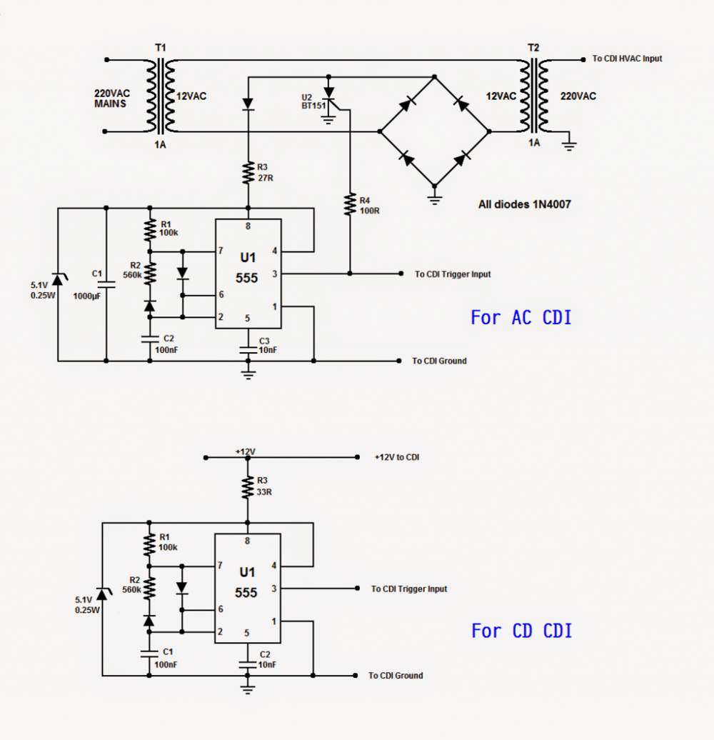
Studying both the circuits will reveal that the lower circuit is the portion of the first circuit. The first circuit is to test AC-CDIs.
Circuit Operation
The transformer T1 converts 220VAC from mains to 12VAC and then T2 re-converts 12VAC to 220VAC.
This set-up is to isolate the rest of the circuit from grid mains. This 220VAC is fed into the CDI's HV Input, replacing the HVAC which is obtained from bike's source coil.
The rectifier bridge converts 12VAC into 12VDC and C1 smoothes it. The SCR U2 is used to stop the 12VAC supply to T2, which will be discussed shortly.
The IC U1 is 555 timer configured as an astable multivibrator with duty cycle about 20% and frequency about 17Hz.
The generated pulse train will replace the triggering coil pulse at fixed rate of (17 x 60 =) 1020 RPM.
The output is fed into the CDI's Trigger Input and the ground is connected to the (-)ve rail. The output is also connected to the gate of the SCR via R4.
Whenever there is a positive pulse, the SCR will temporarily cut-off the 12VAC supply to T2. Hence, 220VAC supply to CDI will be paused. This is necessary to avoid a shorted path when the SCR inside the CDI is dumping the charge of the main capacitor.
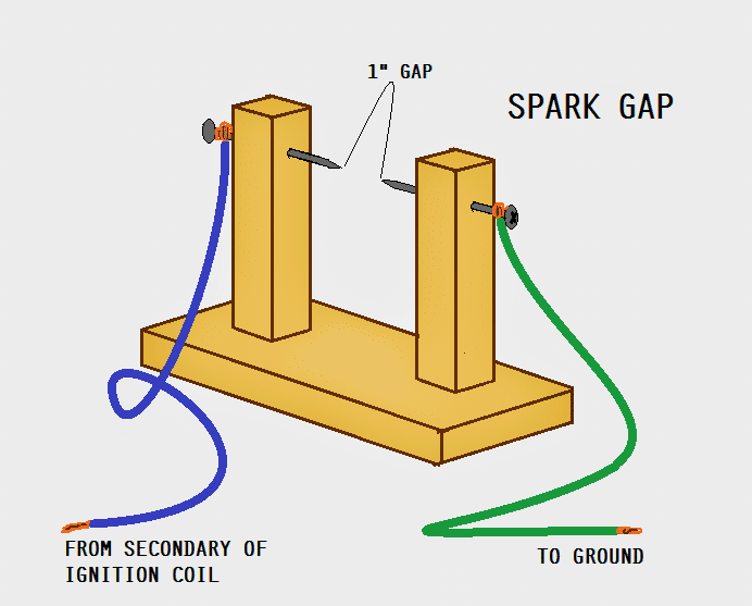
The CDI's output is connected to one end of the primary of an ignition coil. The other end is connected to the (-)ve rail.
One end of the secondary of the ignition coil is connected to a spark gap and the other end is connected to the (-)ve rail.
The second end of the spark gap is also connected to the (-)ve rail. A strong spark across the gap will indicate that the CDI is good.
If the CDI under test is DC-CDI, the lower circuit will be used. The connections will be the same except the power supply will be 12VDC. The HVAC supply is built-in inside the CDI. A good CDI will fire strong spark across the gap.


Questions & Answers
https://imgur.com/a/FLOjsgN
Is that two common grounds be on same wires? Connected to grid ground?
Yes, those are single common connection, but does not need to be grounded anywhere. The ground symbol indicates the common line, that’s all, no need of any grid grounding or earthing…
Hi! I hope you can help me. I’m looking for a tachometer for my Honda generator GX 440 that I’ve had help from you before. I need a tachometer for the single-cylinder generator that I can keep track of the speed. I was thinking of taking the signal from the pickup coil that I normally feed to the CDI board. Do you know of a suitable tachometer that would fit? It should be able to be powered by 12 volts. Best regards Göran
Hi, you can try one of the designs from the following article, whichever you find the most suitable for your application. Yes, the input signal can be taken from the pickup coil….
https://www.homemade-circuits.com/10-led-tachometer-circuit/
Hi! Asking here about my problem. You can delete if it doesn’t fit. Trying to rebuild the ignition on a Honda gx440 generator. The ECM control box has been too expensive to buy. I was thinking of converting to regular ignition. Do you have any tips on how I should proceed? Regards Goran
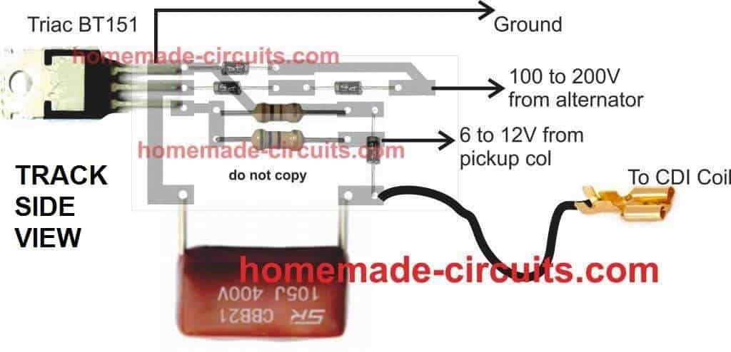
You can try the following simple concept, and implement it in your bike:
https://www.homemade-circuits.com/how-to-make-capacitive-discharge/
This will fulfill the operation you are looking for.
Thanks for the suggestion. Will try it out.
What type of charging capacitor do you recommend?
It should be polypropylene type or PPC, or metalized polyester.
Thanks Swagatam
You are welcome Goran…
Hi again. Do you have any suggestions on the schedule you sent for the CDI ignition if you want to change the timing of the ignition. We would be grateful if you had any tips on that. Regards Goran
Hi Goran,
The simple CDI design which I suggested earlier cannot be modified directly for adjusting the timing. However i have a related article which you can read and maybe customize to work as per your needs. Here’s the article:
https://www.homemade-circuits.com/adjustabe-cdi-spark-advance-retard/
Hello! What do you think what value of the Cx capacitor could be useful to start on a 4 stroke engine 49 cc about 13 hp
Hi, It can be found only through a practical experimentations, it is difficult to suggest without a practical testing…..
Hi! I built the simple CDI ignition that you recommended for testing. It draws a lot of current at rest. Before I even triggered it. Now I tested the construction on the table with a 12/220 transformer connected backwards that I feed the 555 and mosfet. Regards Göran
Hi, are you referring to the circuit from the following article?
https://www.homemade-circuits.com/how-to-make-capacitive-discharge/
Hello! YES.My first post the question about the ignition module with the thyristorHello!.
In the following design which you are referring to, the SCR will not heat up without a trigger. Even when triggered, the SCR will just become little warm, it will never become hot:
Please check your circuit connections properly.
connected according to the diagram, it didn’t work. I’m testing the pcb variant instead. There you have 2 series diodes in the chain to the scr anode.
The PCB version is the exact original design which I have sold 1000s of pieces in the market (long ago) without any problems.
Please check each diode with a multimeter and also check the SCR separately.
Or disconnect the gate of the SCR from the circuit temporarily and check whether it is heating up or not.
In the video I have used the very same PCB assembly for the demo.
Thanks! I’ll let you know when it works.
Ok, thanks!
I hope you don’t think I’m being pushy. I think the connection of the output transistors is a bit strange. Or are there any advantages to it?
I cannot see anything strange in the output transistor configuration, it looks technically correct. If you think something’s not right please explain it?
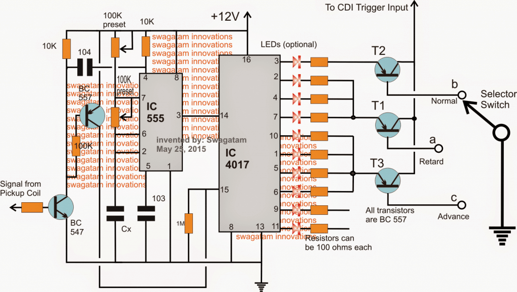
Just a wonder. Isn’t a pull up resistor needed on the base when it is not grounded to turn it off?
The problem will be tuning it for my particular engine. Or is there some basic value to work from?
Thank you for your interest
Yes, a pull-up resistor would be required between the emitter/base of each of the output transistors. Thanks for pointing out the mistake.
Tuning is the crucial part in the above design which will need to be done patiently using meters and oscilloscope until the correct calibration is achieved. Unfortunately, there is no starting value available to me, this will need too be fixed with a lot of experimentation.
Sure, no problem…
Dear friend, I want to build this project since I am a motorcycle mechanic and it would be very useful for me but I have a doubt, does the tyristor interrupt shorting the bridge rectifier, does not cause heating or damage to it or the transformer? I was about to put it together but that doubt arises, thank you very much and greetings.
Dear Carlos, yes it does short circuit the transformer/bridge, you can use a low current transformer to avoid damage to the diodes or the SCR.
Alternatively you could try the last design from the following article:
https://www.homemade-circuits.com/make-this-enhanced-capacitive-discharge/
Thank you very much, that was my doubt, I will arm it anyway to check the operation of the CDI at least at low revolutions, since I can not find any circuit that works simulating higher revolutions, since that is where they tend to fail, but this circuit It will be useful, thank you.
OK, no problems!
congratulations for the super project for a chance could be adapted a potentiometer to simulate the engine rpm in this project and where you could put thanks in advance
Thanks, Glad you liked it, yes that may be possible by replacing the lower diagram’s R1 with a 100K pot, but make sure to connect a 1K resistor in series with it
Unless i missanderstood the schematic, the AC CDI gets his power at 50/60Hz, so it will work only for 3000~3600 rmp max. I’m rigth?
According to me it seems the SCR will fire only 50 times per second, the high frequency from the IC 555 might not help to chop the SCR conduction, because the SCR will be latched until every zero crossing which will force it to work at max 50Hz frequency or less.
Thank you for responding and in the ac cdi it would be possible
yes, it is possible with both the designs
Esta interesante el circuito
gracias
Dear Swagatam
Would you mind letting me know the wattage of all the resisters used in this model?
Regards
Dear Swagatam,
R3 & Zener Diode are getting hot where R3 is getting too hot to touch, in just few seconds. Please advise what to do?
Regards
Dear Ibtihaj, increase R3 to 1K and check the response
Hi Ibtihaj,
All the resistors can be 1/4 watt, CFR 5% resistors.
Okay. Thanks
Can we use ignition coil itself instead of using this wooden model?
the wooden model is used for spark generation just like a spark plug does…
Thank you very much sir
Please I want to know the difference between ups and Inverter, after that can I replace the 7ah ups battery with 200ah?
Thanks Basiru,
UPS has an automatic changeover and is normally suitable for all appliances whereas an inverter may lack both of these features.
yes you can replace a 7ah ups battery with 200ah battery provided the voltage is not altered