A vey basic yet reasonably efficient 1500W PWM based sinewwave inverter circuit can be studied under this post. The design utilizes very ordinary parts to accomplish a powerful SPWM type inverter circuit.
Main Specifications
Power Output: Adjustable from 500 watts to 1500 watts
Output Voltage: 120V or 220V as per the transformer specs
Output Frequency: 50Hz or 60Hz as per requirement.
Operating Power: 24V to 48V
Current: Depending on the Mosfet and transformer Ratings
Output Waveform: SPWM (can be filtered to achieve a pure sinewave)
The Design
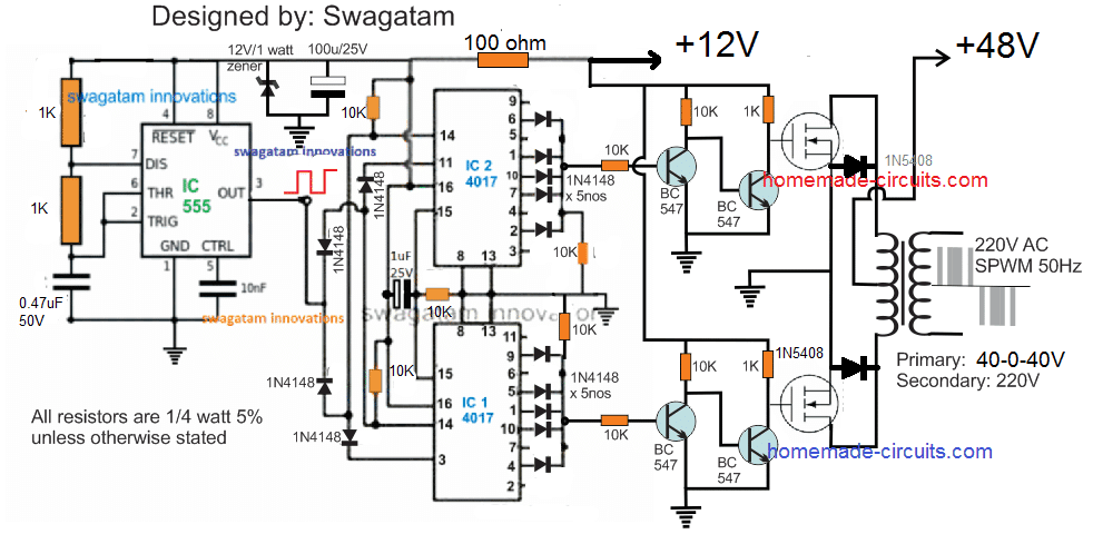
The proposed 1500 watt PWM sinewave inverter is designed using extremely basic concept through a couple of IC 4017 and a s single IC 555.
In this concept the sequencing logic from the output of the IC 4017 are configured by selecting and skipping subsequent pinouts such that the resultant sequencing produces a decent SPWM like switching on the connected mosfets and the transformer.
The complete schematic could be visualized in the following diagram:
The working of the Inverter can be understood from the following explanation:
Circuit Operation
As can be seen, two IC 4017 are cascaded to form an 18 pin sequencing logic circuit, wherein the each negative pulse or frequency from the IC 555 produces a shifting output sequence across each of the indicated outputs of the two 4017 ICs, starting from pin#9 of the upper IC upto pin#2 of the lower IC, when the sequence is reset to initiate the cycle afresh.
We can see that the output of the IC 4017 are intelligently tapped by skipping and combining sets of output pinouts such that the switching to the mosfets achieves the following kind of waveform:

Acording to the waveform, the start and the end sequences can be seen being skipped by eliminating the relevant pinouts of the IC, similarly, the second and the 6th pinouts are also skipped, while the second, 4rth, 5th, 6th pinouts are joined for accomplishing a decent SPWM like pulse form across the outputs of the two 4017 ICs.
Video Proof (100 watt example)
The Objective behind this Logic Configuration
The above shown waveform is selected so that it is able to replicate the actual sinusoidal or sine waveform as closely as may be possible.
Here we can see the initial blocks are eliminated so that the SPWM waveform can match the actual sinewave's initial lowest RMS value, the next two alternate blocks imitate the average rising RMS within a sinewave, while the center 3 blocks tries to replicate the maximum RMS of an exponentially rising sinewave.
When the above PWM format is applied to the gates of the mosfets, the mosfets alternately execute the switching of the transformer primary with the very same switching format in a push pull manner.
This forces the secondary synchronously to follow the induction pattern with an identical waveform which ultimately results in the creation of the required AC 220V, having the above SPWM waveform pattern.
An appropriately dimensioned LC filter across the output winding of the transformer may finally allow the secondary side to achieve a perfectly carved sinusoidal waveform.
Therefore when the resultant output of this SPWM is filtered should hopefully result in the replication of a sinewave output which could be suitable for operating most electrical appliances.
The Oscillator Stage
An ordinary IC 555 astable is implemented here for creating the required clock pulses for feeding the cascaded 4017 ICs and for enabling the sequencing logic across their output pinouts.
The R1, R2,and C1 associated with the IC 555 must be accurately calculated so that pin#3 is able to generate around a 900Hz frequency at around 50% duty cycle.
A 900 Hz output becomes necessary so that the sequencing across the total 18 pinouts of the 4017 ICs causes the BJTs to trigger at a 50 Hz across the two channels, and at around 150 Hz for chopping the individual 50 Hz blocks.
About the Mosfets and the Transformer
The mosfets and the transformer of the above explained 1500 watt SPWM inverter circuit are the two elements which determine the total power output.
For getting a 1500 watt output make sure the battery supply is not less than 48V, at 500 Ah, while the transformer could be anywhere around 40-0-40V/ 40 amps.
The mosfets can be IRFS4620TRLPBF each if 48V battery is used, a pair of these mosfets would be required in parallel on each channel for ensuring proper delivery of the full 1500 watts at the output
If you have any doubts or personalized queries, please feel free to add them in the comments below for getting quick pertinent replies.



Questions & Answers
dear swagatam i really thank you for great work in helping people like us who are born engineers but could`nt afford to study in a Tertiary institution, to navigate our way around in electronic circuit design.
I conceive an idea, pls check if such idea is design-able.
i called it P.P.S.S that is permanent power supply system,this is it.You create two inverter system that works in flip flop manna to power a connected load,one will be working while the other is charging,when its battery reaches a certain discharge level the system flips and the other takes over duty without any interruption to the connected load.to reduce cost one transformer may be use for the two of them.
secondly how can we partner in Nigeria to enter into production of affordable power supply system for the poor people who are paying with their blood just to light candle.
Dear Savior, I am glad you liked my website.
However the idea you have conceived may not work, because the power output from any inverter will be always less than the input battery power consumption, so ultimately the power exchanges between the two inverters will keep reducing until the both the batteries are unable to get charged any longer from the inverter outputs.
I am really sorry, partnering may not be possible due to the work pressure that I have to handle in the present moment, although I appreciate your offer very much and wish we could partner for this noble cause.
Thanks a lot mr swag,for the reply ,there are some design i have put-up to that effect using DPDT relays and low battery cut-off protection circuit ,i will send an attachment to you when i conclude.well done!
You are most welcome saviour! please keep up the good work
sir swatagam do you have the complete diagram and omponetguide and pcb design for this 1500watts inverter can u please send it o my email thank you it much appreciated…
Fred, I have updated the diagram with more details, please copy the parts list from the diagram, everything has been included according to me….if you have any further doubts, please let me know.
PCB design is at the moment not there with me, if possible I’ll try to update it soon…
sorry youupdated already the diagram but one more questions sir the mosfets where is the gate drain and source canyou please put it on each channel thanks..nd more power sir
Fred, the pins which are connected with the transformer are the drains, the pins which are connected with the BC547 are the gates, and the ones which are connected to the negative or ground line are the sources of the mosfets.
Olá sou do Brasil e acompanho as suas publicações continui com esse bom trabalho tem ajudado muita gente eu fiquei interessado no projeto do inversor senoidal se possivel poderia me enviar o projeto completo por gentileza obrigado
Sir can i run the above inverter circuit with 12v battery by changing 48-0-48 transform er with 12-012 transformer
bashir, it is possible, but the transformer will need to be rated at 9-0-9V
..and the mosfets could be replaced with IRF540
hello sir do you have any idea about self running generator thanks
sorry I do not have any idea regarding this concept
Good Day,
Have you tested this design or the arduino spwm design?
yes those are tested designs
In the working of this circuit you have 40-0-40v transformer to be used with 48v battery supply, shouldn’t that only be used for a square wave inverter?
with a spwm inverter shouldn’t the transformer be 24-0-24 for a 48v battery supply?
so as an example If I was to use a 12v battery supply transformer would be 6-0-6v, is that correct?
you will have to identify the average ON time % of the SPWM, multiply this % with the battery voltage to get the transformer primary value
It will depend on the average value of the SPWM voltage with respect to the battery voltage. The resultant value can be used for determining the transformer secondary voltage value.
You can the related information below:
https://www.homemade-circuits.com/inverter-voltage-drop-issue-how-to-solve/
Sir
Witch transformer should i use for 1000w with 12v 200AH battery
Thank you
Fardin, with a 12V battery the transformer will need to be around 1000/12 = 83 amps, 7-0-7V
Sir
Do i have to change the mosfets?
Yes, you can try the following specs:
https://www.homemade-circuits.com/55v-110a-n-channel-mosfet-irf3205/
Sir
From ic1 i’m getting around 6.6vac gate voltage
And ic2 i’m getting around 5.1vac from gate
Why this is happening?
And my ic2 is getting warm
My suppy voltage was 12vdc
Fardin, slight voltage difference at the gates may not be critical, but if your IC is getting warm then that could be an issue. I hope you have connected the reverse diodes across the mosfets, if not please do it and check again.
Also make sure the IC Vcc is not over 12V.
Hi Swag,
What is the amp rating on your 40-0-40 transformer
Hi Giel, just divide the required output wattage with 40, this will roughly give you the required amp capacity of the transformer
Pls sir I need a 48v/5kva pure sine wave inverter circuit that has an automatic battery shut down and no load sencing.
Jojo, you can try the above explained concept, the battery shut-off circuit can be easily included later on one the inverter is finalized
Pls swag,I av tried this circuit but its not pure sinewave.pls I need your best PURE SINEWAVE CIRCUIT for 5kva/36v battery.
JoJo, how did you check the output waveform?…you will need to check it with an oscilloscope and with a load connected with the transformer. For further improving the results you may try connecting a 105/400V capacitor across the secondary winding output.
By the way it will not give a best sineave, but much closer to a sinewave
I tested it with load like refrigerator and air condition but it did not work fine.pls help me with a better version that is pure sine wave
sorry that’s not the way to test and fine tune an inverter output, you must do it through an oscilloscope by analyzing the waveform and then tweak it through a LC filter circuit at the output to achieve the required output. If you do not have an oscilloscope then please do not attempt any of the sinewave inverter circuits.
Swag,most engineer does not have oscilloscope but I think you will have a design that has lc filter,so pls help me with the one that has giving you good result. Thanks
Jojo, while dealing with a sinewave inverter circuit, an oscilloscope is mandatory, otherwise it won’t make sense.
Anyway, you can select one of the following designs as per your preference, but all these will again require an oscilloscope for confirmation of waveform and will require an LC filter at the output, I do not have the calculations for the LC filter it will need to be done through manual experimentation.
https://www.homemade-circuits.com/?s=SPWM
here’s another good choice
https://www.homemade-circuits.com/pure-sine-wave-inverter-circuit-using/
Thanks so much swag.Its a final year project and my certificate depend on it.I will try it again.
wish you all the best jojo, if you have any further doubts don’t hesitate to ask them.
Good day Mr. Swag, can the above concept be implemented with 3kva and above? If yes, what specs of transformer and MOSFETs will you recommend.? And how do I go about the filter part. Thank you, awaiting your reply.
Hi King, that is possible. Divide 3000 with battery voltage this will roughly give you the transformer primary current.
For the mosfet make sure its continuous current and voltage ratings are much higher than transformer rating.
Battery Ah should be 5 to 10 times higher than the calculated value of transformers current rating
https://www.homemade-circuits.com/how-to-calculate-and-match-inverter/
Sir swag,pls i dont know how to configure this (AND gate) with this microcontroller. Pls give me any circuit relating to AND gate.check the schematic here. 4.bp.blogspot.com/-Llu4f6lzODA/UR-Gya40gGI/AAAAAAAAAbM/nuos2eLOTSs/s1600/pic+config.png
Please Google for “AND gate IC” and integrate the selected IC pinouts accordingly
Thanks sir.I have Google it but I didn’t understand how to use it.pls give me any one with the pins out that you know according to my description of that diagram.
you can use 7808 IC which has AND gates inside it, just check which pins connect with the those oval shaped designs inside the IC, and replace those pinout with your AND gates shown in your inverter circuit
7808ic is a voltage regulator. So how can it work as AND gate?
sorry, it is 7408 and not 7808
Dear Swagatam:
Thanks a lot for your useful info on electronics and guiding us to this course.
would you please explain more about how to parallel transistors??
and how to connect them in series ???
thanx a lot
Your Sincerely Saeed
Thanks Saeed, I already have one related article posted in this website which explains the right ways to connect transistors in parallel, you can read it here:
https://www.homemade-circuits.com/transistor-facts/
Connecting transistors in series is normally not practiced in electronic circuits and it may not be recommended also.
can the mosfets be replaced with IRF540?
yes, if your requirement is within the mosfet’s rating specs