
In this post we learn how to generate sine wave pulse-width-modulation or SPWM through Arduino, which can be used for making a pure sine wave inverter circuit or similar gadgets. […]
Search Results for: SPWM
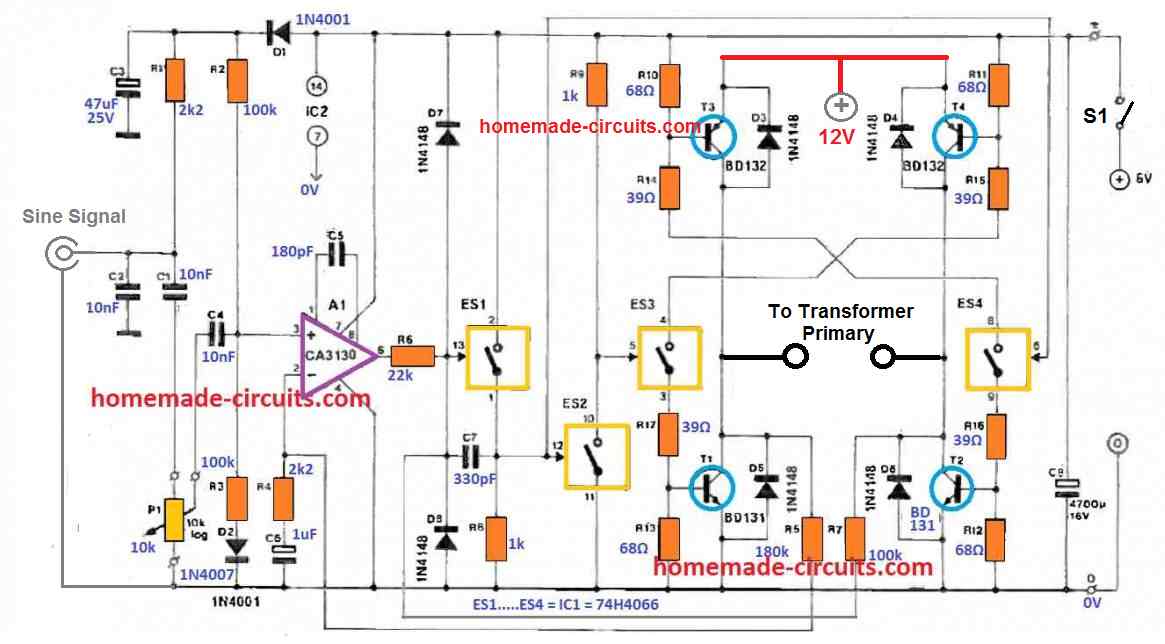
Sine wave PWM (SPWM) Circuit using Opamp
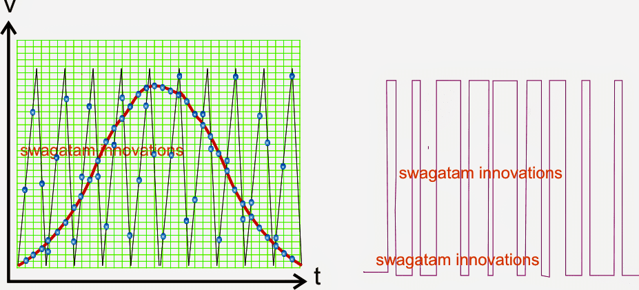
SPWM refers to Sine Wave Pulse Width Modulation which is a pulse width arrangement in which the pulses are narrower at the start, which gradually get broader at the middle, […]
Design your own Sine Wave Inverter Circuit from the Scratch [Tutorial]
In this post we will discuss comprehensively regarding how to design a sine wave inverter without any form of coding or complex circuit designs. The included designs are simple yet […]
EGS002 Datasheet, Circuit Diagram Explained
The EGS002 is a single-chip inverter controller that is widely used in small-scale inverter applications. Here are some general datasheet for the EGS002: General Datasheet The EGS002 is designed to […]
Class-D Sinewave Inverter Circuit
A sinewave inverter using class-D amplifier functions by converting a small sinewave input frequency into equivalent sine PWMs, which is finally processed by an H-bridge BJT driver for generating the […]
500 Watt Inverter Circuit with Battery Charger
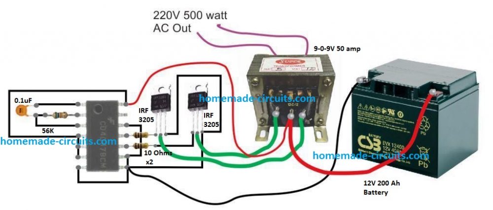
In this post we will comprehensively discuss how to build a 500 watt inverter circuit with an integrated automatic battery charger stage. Further in the article we will also learn […]