The proposed 10 band graphic equalizer circuit can be used in conjunction with any existing audio amplifier system to get an enhanced 10 stage audio processing, and customized tone control.
The circuit can be easily converted to a 5 band graphic equalizer by simply eliminating 5 stages from the shown design
The Circuit Concept
A graphic equalizer is a type of complex tone control circuit which can be applied to smooth out or enhance the frequency response of any hi-fi audio amplifier, or in a guitar effects unit. To be precise, the unit can prove effective in virtually any form of audio application.
The unit is quite simple to use. All one has to do is feed the TV or PC audio input to this circuit and hook the output with the existing home theater amplifier.
Next, it would be just a matter of adjusting the given 10 band controls and enjoying the vastly improved sound quality.
You would be able to tailor the sound as per your preferred tastes.As an example, the midrange controls of the equalizer can be adjusted to highlight dialogue or in order to reduce the harshness over a particular range of voice audio.
Or perhaps you can roll off the high pitched even to further extents in case you wished, or simply heightened the bas boost to your liking.
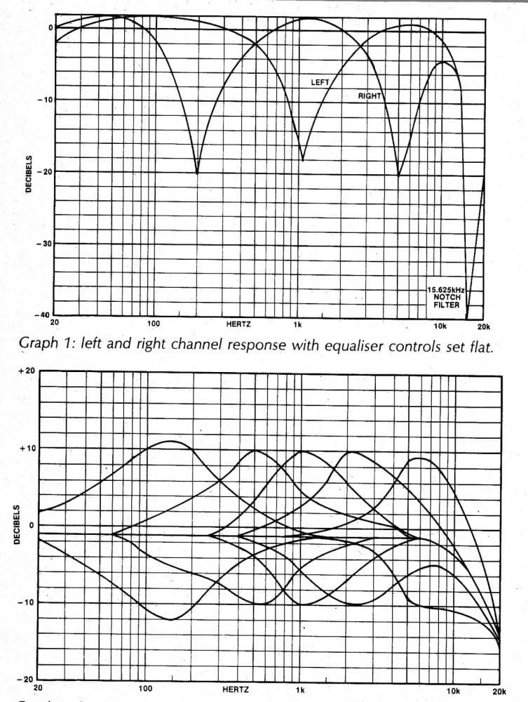
Typically the controls would be able to provide upto 10dB of boost or cut at nominal center frequencies of 150Hz, 500Hz, 1kHz, 2kHz, 5kHz, 7kHz, 10kHz, 13kHz, 15kHz, 18kHz.
The circuit also includes a fixed 10kHz low pass filter stage for cancelling out unwanted noise such as hiss or other high frequencies disturbances.
How the 10 band graphic equalizer circuit functions
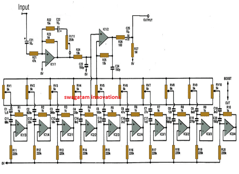
Referring to the given circuit diagram we can see that the associated opamps form the main active component responsible for the required optimizations.
You will notice that all the 10 stages are identical, it's the difference in the values of the incuded capacitors and the pot which effectively varies the processing leves across the various stages.
For analyzing the operation we may consider any one of the opamp stages since all of them are identical.
Here the opamps act as "gyrators" which refers to an opamp circuit which effectively converts a capacitive response to an inductance response.
Consider an AC voltage source Vi connected to the opamp stage. This pushes a current Ic via the capacitor (C1, C2, C3 etc), which constitutes a proportional voltage across the connected ground resistance (R11, R12, R13 etc).
This voltage across the ground resistance is conveyed at the ouput of the opamp.
Due to this the voltage across the feedback resistor (R1, R2, R3 etc) becomes equal to the difference between Vin and Vout which causes current to flow via the feedback resistor and back into the input voltage source!
A careful assessment of the phases of the above developed current would show that as Ic leads the voltage Vin (as it can expected for any capacitive circuit) the net input current that may be the vector sum of Ic and Io in fact trails the voltage Vi.
Using Capacitors as Tuned Inductors
Therefore this implies that in effect, the capacitor C has gotten transformed into a virtual inductor due to the actions of the opamp.
This transformed "inductance" may be expressed by the following equation:
L = R1xR2xC
where R1 = ground resistance, R2 = feedback resistance while C = capacitor at the non-inverting input of the op amp.
Here C would be in Farads and the resistances in Ohms.
The pots effectively vary the input current to the opamps which results in a change in the value of the above explained "inductance", which in turn results in the required music enhancement in the form of treble cuts or bass boosts.
Circuit Diagram
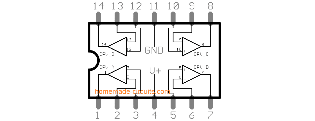
LM324 IC Pinout Details
Parts List
- All resistor are 1/4 watt 1%
- R1----R10 = 1K
- R11---R20 = 220k
- R21 = 47K
- R22 = 15K
- R23, R27 = 1M
- R24, R25 = 10K
- R26 = 100 ohm
- RV1----RV10 = 5K pot
- RV11 = 250K pot
- All pF and nF capacitors are metallized polyester 50V
- C1 = 1.5uF
- C2 = 820nF
- C3 = 390nF
- C4 = 220nF
- C5 = 100nF
- C6 = 47nF
- C7 = 27nF
- C8 = 12nF
- C9 = 6.8nF
- C10 = 3n3
- C11 = 68nF
- C12 = 33nF
- C13 = 18nF
- C14 = 8.2nF
- C15 = 3.9nF
- C16 = 2.2nF
- C17 = 1nF
- C18 = 560pF
- C90 = 270pF
- C20 = 150pF
- C21, C22, C25 = 10uF/25V
- C23, C24 = 150pF
- Op amps = 4nos LM324
Response Curve for the above 10 band graphic equalizer design
Simplified Version
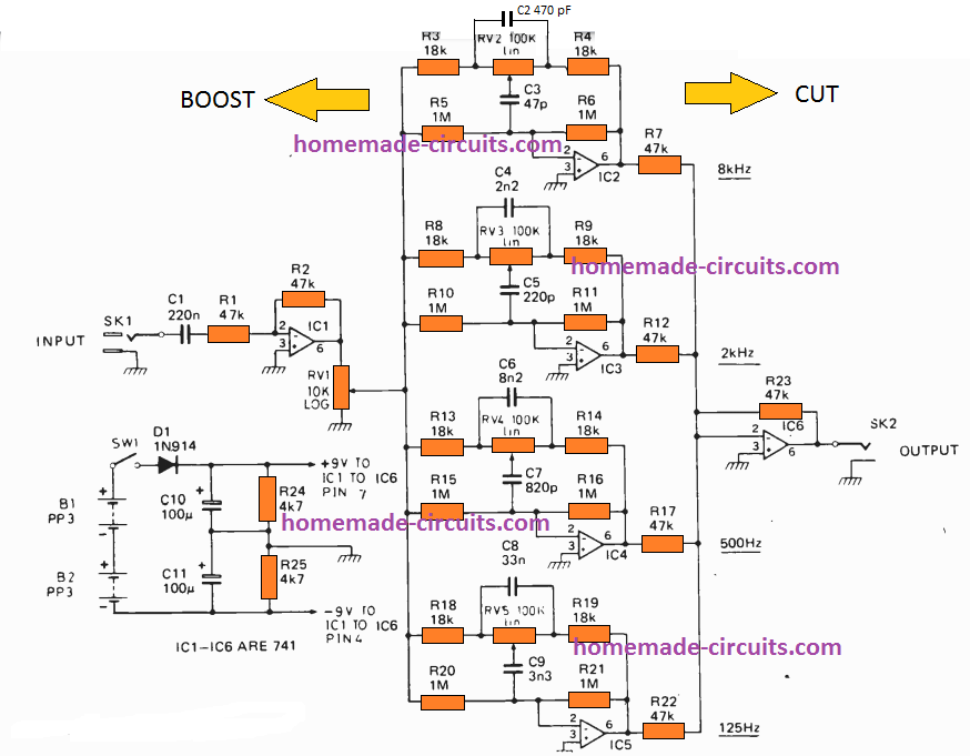
The simplified version of the above explained graphic equalizer can be witnessed in the following image:
Parts List
RESISTORS all 1/4W, 5%
R1, R2 = 47k
R3, R4 = 18k
R5, R6 = 1M
R7 = 47k
R8, R9 =18k
R10, R11 = 1M
R12 = 47k
R13, R14 = 18k
R15, R16 = 1M
R17 = 47k
R18, R19 = 18k
R20, R21 = 1M
R22, R23 = 47k
R24, R25 = 4k7
POTENTIOMETERS
RV1 10k log slider pot
RV2, 3, 4, 5 … . 100k linear slider pot
CAPACITORS
C1 = 220n PPC
C2 = 470p PPC
C3 = 47p ceramic
C4 = 2n2 PPC
C5 = 220p ceramic
C6 = 8n2 PPC
C7 = 820p ceramic
C8 = 33n PPC
C9 = 3n3 PPC
C10, C11 = 100µ 25V electrolytic
SEMICONDUCTORS
IC1-1C6 = 741 op amp
D1 = IN914 or 1N4148
MISCELLANEOUS
SW1 spst miniature toggle switch
SKI, 2 mono jack sockets
B1, 2 9V 216 batteries
5 Band Active Equalizer Circuit
According to the circuit architecture shown below, the input signal is capacitively linked to the non-inverting input of IC1a, which is used to buffer the signal since at this point a low impedance is needed to reduce noise pickup on the potentiometer wires.
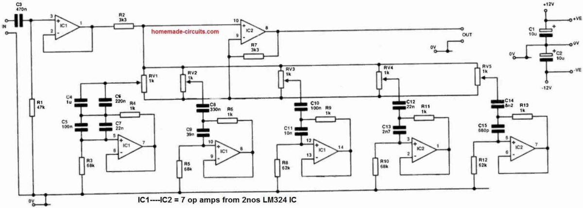
For now, let's ignore the potentiometers. The signal is sent through R2 to IC2c, which acts as a unity-gain buffer DC-coupled to the output.
If every potentiometer is set to its middle position, any loading on the sliders will pot down the input signal to the non-inverting input of IC2c, while also pot down the negative feedback and producing a gain that compensates for the potting -down of the input signal.
Consequently, we still have unity gain at all frequencies in this situation.
The system displays a net gain at 206 Hz if the slider RV2 is pushed to the inverting input end of its range.
This is because the effect of potting down the negative feedback is, at resonance, considerably stronger than the potting -down of the input signal.
The input signal is potted down but the negative feedback is not, therefore there is a decrease in the frequency response at 206 Hz when the slider turned to the non-inverting input end of its journey.
Each and every potentiometer follows the same logic.
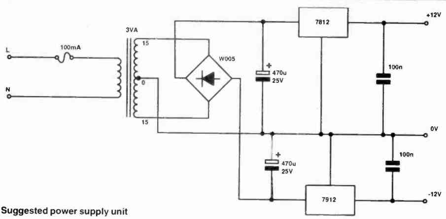
In order to reduce the impacts of crosstalk through the power supply, local decoupling is offered on the board.
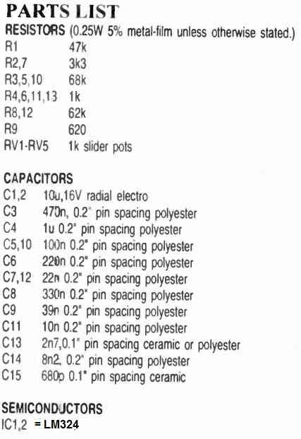
Parts List
5 Band Passive Equalizer Circuit
A very neat and reasonably efficient 5 band graphic equalizer circuit using only passive components can e built as shown in the following diagram:
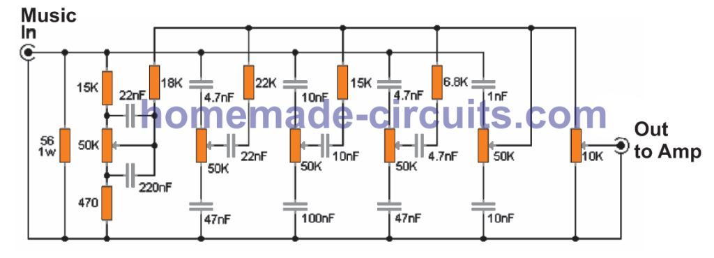
As can be seen in the figure above, the 5 band equalizer has five potentiometers for controlling the tone of the input music signal, while the sixth potentiometer is positioned for controlling the volume of the sound output.
Basically, the shown stages are simple RC filters, which narrow or broaden the frequency passage of the input signal, so that only a certain band of frequency is allowed to pass, depending on the adjustment of the relevant pots.
The equalized frequency bands are 60Hz, 240Hz, 1KHz, 4KHz and 16KHz, from left towards right. Lastly followed by the volume control pot control.
Since the design does not use active components this equalizer is able to operate without any supply input. Please note that if this 5 band equalizer is implemented for a stereo or multichannel system, it may become necessary to set up an equalizer in the identical manner for each of the channels.
Parametric Equalizer Circuit for Enhanced Effect
If you are not impressed with the above 10 band graphic equalizer results, then the following simple parametric equalizer circuit will surely make you feel a lot happier.
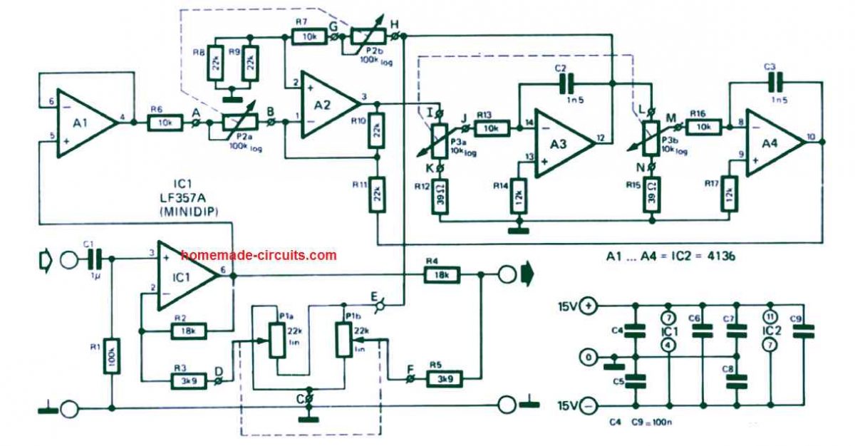
Audio input is sent from left side at the input of C1, while the enhanced equalizer effect is acquired from the right side R4 end which must be connected to the power amplifier.
The dotted lines indicate that the relevant potentiometers must be dual type pots, and must move concurrently.
The effect from such parametric equalizers or filter circuit is said to be similar to the effects that we normally get in concert halls, and auditoriums.


Questions & Answers
am looking at building an audio amplifier that the user can adjust as needed (senior citizen).
Watching tv and deciphering the audio sometimes when actors are talking.
Looking at the 5 or 10 band equalizer circuit or the Parametric Equalizer Circuit for Enhanced Effect.
For a low noise op amp looking at the TL074 SINGLE SUPPLY.
a condenser mic and 30ohm Koss headphones,
what happened to the enhanced bandpass circuit?
Sorry, I did not understand your question?
Here’s one example of a bandpass circuit:
https://www.homemade-circuits.com/build-this-subwoofer-amplifier-circuit-mini-ground-shaker/
in your ENHANCED AMPLIFIER drawing the resistors are hard to read (R12, R14, R15, R17)
Contemplating using the LM4862 and/or MAX4466
Here’s the enlarged version of the diagram, please let me know if it is still not clear:

Sure, I think the following option would work better than a TL074:
https://www.homemade-circuits.com/lm4862-amplifier-circuit-better-lm386-alternative/
For MIC integration you can consider the MAX4466 module option:
https://www.homemade-circuits.com/explained-max4466-electret-microphone-amplifier-module-with-adjustable-gain/
I dont understand why you say that a 10k pot is not posible to make the 10 band equalizer can you explain me? I see this is a voltage divider that controls the current that go through each stage
If you use 10k, it will still work but may not produce the best results. All the parts are calculated ideally for generating optimal results, changing it can affect the audio response and quality.
I experimented with a low noise tone control with 5k log potentiometers and the bass values for the bass capacitors are 10uf and 1uf. The resistors in this case become 470ohm and 47ohm. We measure the noise in ohms at very small millivolt signals. High values of 100k produce a lot of noise. Now it also depends on the schematic and where the tone control stage is located.
Thanks for the feedback!
Regarding the last circuit diagram of “5-band Passive Equalizer Circuit”, the problem of using a volume equalization circuit composed of RC:
1. What is the test input voltage (mV)? V? Well?
2. What is the power requirement of the resistor in the picture?
3. What type of potentiometer is it?
4. Is the capacitor a polyester capacitor or a ceramic capacitor?
5. In this circuit, what formula is used to calculate the frequency value?
6. Are there any other precautions?
For the last passive equalizer circuit:
1) Input voltage should be above 100mV.
2) All resistors can be 1/4 watt CFR.
3) Potentiometers are standard linear type.
4) Capacitors can be ceramic or polyester.
5) Formulas are all RC based, exact formula is not available.
6) No other precautions are required.
Thank you! Bro!
Looking forward to more new works from you!
You are welcome Khan!
For passive 5 band equalizer, what was the recommended type of the resistor and caps?
The recommended type is MFR 1% for the resistors and metallized polyester for the capacitors.
How do you change the value of the frequencies? Like, having the EQ centered at 1.2kHz instead of 1kHz. Thanks!
Good Day Swagatam!
I wish to apply to 10-band GE circuit to measure the frequency distribution of the sound of a church choir and several instruments as it actually sounds in the church hall. The idea is to feed the output of a microphone (Shure SM57) placed in the center of the church hall while the choir is singing as input to the GE. All bands will be initially set to the midpoints of their variable pots’ ranges. I have obtained 10 VU meters, which are physically ammeters with the meter face calibrated in deci-Bells. These will be connected in series with each of the 10 variable pots.
The display of each VU meter can then be used to measure the relative volume of each of the 10 frequency channels. If there is too much volume above midrange and not enough at lower frequencies, then the lower frequency instruments can have their volume increased. Since everyone’s ear is different, this device should provide an objective measure of the balance of frequencies in the hall.
Each VU has a resistance of 500 ohm and reaches 1 mA at full scale. Suppose however that in the circuit above, the currents at full range of the VRs range from 10 mA at RV1, to 50 mA at RV 10, all of which are beyond the limit of the VU meters. Then my measurements would actually alter the output I am trying to measure! So perhaps measuring current is not correct!
Q1: should I not measure the voltage across the RV instead of measuring the current?
Q2: where should I connect each VU meter? I say from the high input of IC 1/2 to the “pointer” setting of each RV1-10. Is this right?
The high input to IC 1/2 is common to the base of each of the RV1-10. The low input to capacitor C24 is common to the output of all RV1-10. Only the “pointer” of each RV will show a variation of voltages across each RV. If I connect from pointer to C24, then that VU meter will measure lowest voltage when the pointer setting is high. If I connect from the high output of IC 1/2 to the pointers, then when the level of an RV is increased, so will the voltage across each VU.
Please let me know if this is the right way to go about this project. I am a mechanical engineer and have worked with small breadboard IC 555 circuits before. I know how the selection of R and C values is key to setting the frequency limits of each band of EQ.
This is a great circuit and looks similar to my Kenwood GE-54 graphic equalizer with 2×10 bands.
Best regards,
Arthur
Thank you Arthur,
Unfortunately, you cannot touch anything on the internal side of the circuit that can severely affect the working conditions of the opamps. Meaning the VU meters cannot be connected anywhere inside the circuit.
If your VU meter is a 1 mA ammeter then probably it can be connected at the input side in series with the capacitor C21.
If your VU meter is a voltmeter then probably it can be connected parallel to R27.
These are my views only, if you think I am wrong, please feel free to clarify it.
Ahhhh, I see. Even a high impedance voltage measurement across the RVs would cause the OPAmps to perform otherwise than expected. And if we measure externally as you suggest, we only get the average frequency response, which our ears are perfectly capable of assessing.
So perhaps the 5-channel Passive Circuit can have voltages across each RV to be measured without distorting the signal? 5 bands would be better than just one! And it’s easier to build.
Yes, opamps are very sensitive devices, so any external circuit coming in contact with their input pins can cause performance issues. However, if you have mA meter as the VU meter you can try connecting them in series with the center wiper leads of the RV1 pots, this shouldn’t hamper the opamp function in any manner and also fulfill the need, I guess.
Yes, that’s the approach I thought best after studying the circuit diagram for awhile. It will be a few weeks until I get something built. I can check back in once that is done. Thanks!
Sure, no problem!
Hi Engineer.
I wanted to make the equalizer of the first scheme. the criticality lies in the potentiometers. I found linear ones at an acceptable price, but only 10 kO. My question. Is it possible to replace? If possible, what modifications to the schema should be brought. Thank you
Hi Rosario,
The circuit parts cannot modified for a 10K pot. For best results you must use 4k7 or 5K pots only. Another idea may be to add a 10K fixed resistor across the end terminals of your 10K pots so that they work like 4k7 pots.Or 10K resistors between the center and the outer terminals of the pot.
Thank you
Thanks sir for teaching
please Ineed aformula for calculating frequency in equalizer circuit (as 5band eq above)
Hi mchina, unfortunately the frequency formula is not available with me, I have provided the inductance formula which allows a passage a specific range of frequencies and suppresses other ranges.
Hi sir, I need gerber file for this equalizer project please help out.
Hi Shahid, Sorry I do not have the gerber files for this circuit.
Hello Sir i need a stereo 10 band equaliser circuit with pcb layout with good effect if any circuit pleace guide me
Ravichandren. K K
Hello KK, the circuit presented in the above article will provide a very good equalizer effect. You can create two of these units to fulfill your stereo requirement. However, unfortunately I do not have a PCB layout for this design.
Hello,
Am abasifreke essien, pls I need help, i wanan be train on circuit designing& circuit analyzing. Thanks.
Have gone through the knowledge &experience share in diz platform indeed is a wow.. Though most them in a short while I will understand…
Pls. Accept me!
Hello, Abasifreke welcome to this blog, you can learn by posting comments, asking questions and by building and testing small circuits initially.
Hello,
I have found a very good circuit with transistor, what lot of producters like samsung are using.
And in there are capacitors also, but I think without any bad compliment what I found is better and requiers much more fewer element, and in this case is not as big on the plate.
If you are interested I can send to you and maybe you can help me to say the truth:).
Have a nice day!
Gábor
Hi, thank you and I appreciate your offer to provide me the transistor regulator, however I already have many good transistorized regulator circuits in this blog, so it’s fine! No problem!
I can do the supply for the op amps with an other circuit. I have to use an inverter from what does 30V from auto accu. 12V and after this again regulated to DC. After I use a stabilized voltage tranzistor circuit with the difference that on the B I use a resistor and a capacitor not diode. As I recognised many of the company using this to reduce incomming noise and this also chilling the interferency between the op amps.
Am I thinking good Sir?
Thank you for answer!
Gábor
If your power supply is regulated and has negative positive both supplies, then it is fine you can use it to power the op amp circuits.
Hey again!
Well, my question is: I want to supply this circuit from an auto accu. I have to use an inverter for more voltage, a so called stabilised voltage supply at the out what I can plan and implement.
This is just a thing. But, after the inverter I have to use again a AC/DC regulator cuz the opamp is functioning with nearly linear signal. Okay, he does have a tolerance to Frequency depends on producer and type. But I want to be sure this is why I want to implement a transistor circuit what is capable to filter ingoing noise and stabilises the interfequency and Voltage stability between the 5 opamp. <—huh this is my plan. Do I think it good? I recognise that your filter with the many of Capacitors also working on the +15..-15 circuit but I want to do otherwise.<— It is also a way what can be followed?
Thanks for answer, have a nice day. I
Hello, yes you can implement a transistorized voltage regulator. You must also keep the capacitors which are shown in the circuit diagram for proper filtration. The capacitors are required otherwise there may be a chance of noise getting inside the op amp circuit.
Sorry, that I have got an other question!
Right from the Out is an other circuit. May it be that this is the voltage support for the opamps?
And I just figured out that when this is the voltage support then it may be that it can be do otherwise?
Because I have got other ideas to do the 15V voltage and the -15 voltage I mean summa 30V for the opamps function voltage support.
Thanks a lot!
Gábor
Yes the other small circuit at the bottom right shows the supply details for the op amp supply pinouts. You can use voltage from 6V to 15V
Dear Sir!
What does it mean the circle with a line in it and a circle with line only on the two side around the circle?
I speak about the last circuit, the enchanted equaliser.
And where comes out the signal here in the same circuit? I mean it is okay that you use a Power equaliser, but were are the out signals? ON C9 Capacitor?
Thank you very much, Gabor
Dear Gabor, please don not worry about the circle with line marking, it only shows a few connections, that you have to make externally. that’s all. Out is from the black arrow and the ground line.
Is it possible to use small directional microphone as input to the equalizer and use it as a hearing aid?
Yes that’s possible!