The LM386 based amplifier is still very popular as one of the smallest sized amplifier chips. However, the LM386 is not perfect and has a few drawbacks and limitations.
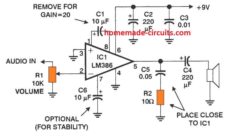
As shown below, the LM386 works with large electrolytic capacitors, which makes it bulkier and costlier, and causes it to be prone to distortions with age.
Another flaw with LM386 is its input impedance which seems to be very high, allowing the chip to be much vulnerable to oscillations if the inputs are not sufficiently isolated from the output.
Its voltage gain of 20 (or 200 by inserting an additional capacitor) looks quite high for line input level (1 V RMS) and this results in further oscillation issues.
On the other hand, the LM4862 IC is more advanced and slightly more powerful compared to LM386 and it works without any electrolytic capacitor.
Main Features of LM4862
It is designed to deliver 0.675 watt into an 8-ohm speaker with a total harmonic distortion of 1%.
When operated at slightly lower power levels, the distortion is reduced to negligible limits.
Another great feature of the IC LM4862 is its automatic thermal shutdown which protects the chip from damage even if the output is overloaded or short circuited.
This circuit requires just a single 5 V supply for the operations. The input impedance of LM4862 is comparatively low and can be suitably adjusted externally, which ensues that the oscillation issue is kept to minimal.
Internal Layout
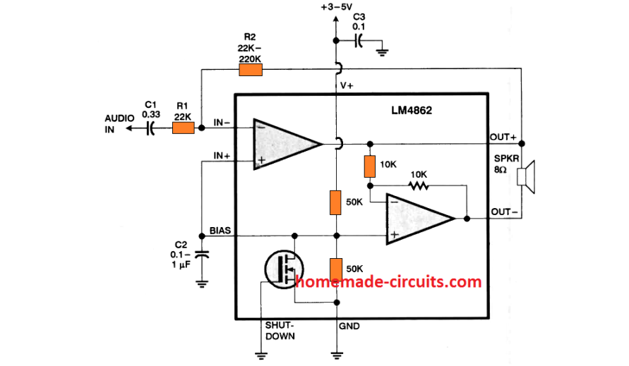
The following figure shows the internal structure of the chip LM4862. The output of the IC LM4862 drives the speaker in a differential mode, which involves opposite push pull waveforms driving the speaker across the two output terminals. This differential topology is commonly recognized as BTL (bridge -tied load).
How the LM4862 Works
In the BTL operation the two terminals of the speaker are alternately toggled with a +5V and a 0V depending on the music frequency. This means, the amplifier is able to generate a total of 10 volts swing across the speaker from a 5 volt supply. This is just enough to create a impressive volume of music volume over 4 inch full range speaker.
The chip will work with supply voltage ranging from 2.7 V to 5.5 V. Which means the LM4862 can be powered from two or three 1.5 V AAA cells or a from a computer 5 V USB, or simply from your mobile phone charger.
But remember, the supply must not exceed 5.5 V, and therefore even a 6 V supply can permanently damage the chip.
Total current consumption of the chip can be expected to be around ranges 5 mA in the absence of a music input. and to around 250 mA when it is operated at its maximum volume limit.
Power supply ripple rejection is superb, which is greater than 50 dB when C2 = 1µF.
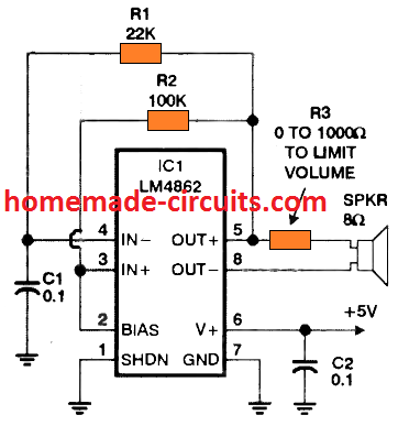
How to Make an Amplifier using LM4862
A general LM4862 based amplifier circuit can be in the following figure.
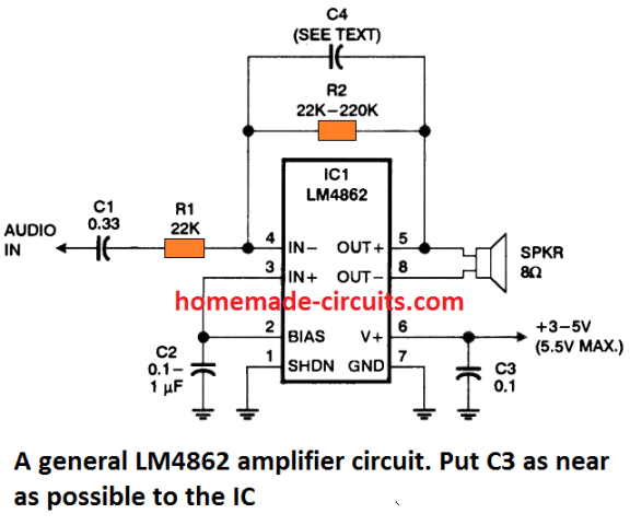
It looks very simple without the use of any electrolytic capacitors; which allows it to be cheap and yet have a high-fidelity audio output.
Basically, C2, works like the bias bypass capacitor, which can be a tantalum electrolytic; blocks the audio signal through it.
If possible a 100 µF electrolytic could be added parallel with the C3 to increase stability when the IC is operated with batteries or a poorly regulated power supply. The voltage gain is determined by 2(R2 /R1) that must not be exceed the value of 20.
You can expect the sound quality to be the best when R2 = R1 and the gain is 2. This is exactly what must be followed to drive a speaker when the input is 1 volt from a line input or a headphone jack 3.5 mm.
In case the gain is made higher than 5, it may be necessary to add a bypass capacitor C4 across R2 to prevent oscillation. This can be a 5 pF capacitor, although up to 22 pF capacitor can also be used. But higher values than this may cause problems.
Typically, smaller value resistors can be used like R1 = 4.7K and R2 = 4.7K to 47K, when the input is fed from a low impedance supply. The following image shows us the component values for a few typical typical amplifier set ups.
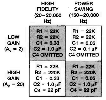
Note that, the design of the amplifier becomes more efficient in terms of cost and power saving when the bass response is kept at its minimum, although that would also mean the absence of the heavier low frequency notes.
The LM4862 is specified to work with at least a 8 ohm speaker, lower ohms might also work such as 16 ohm, 32 ohm, or 64 ohm speaker, but that may cause the power output to be significantly less.
If you wish to operate the speaker as a single ended output by grounding its one end, you might need to add a series capacitor with the other end of the speaker which is connected with the IC output as shown below:
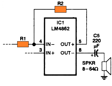
But single ended operation may drastically reduce the power output from the speaker compared to the differential mode.
Using the Shutdown Pin
Normally, the shutdown pin#1 is connected with the ground line in normal. However, this specific pin can be configured with a button to implement a "mute" function without the need of putting a switch directly on the signal line.
Using the Bias Pin
The bias pin#2 is terminated as the output from an internal voltage divider which is used for maintaining the positive inputs of both the op amps at half the supply voltage so that it becomes possible to power the circuit with a single supply.
The bias pin2 may be further used to bias a couple of more op amps as shown indicated in the following figure.
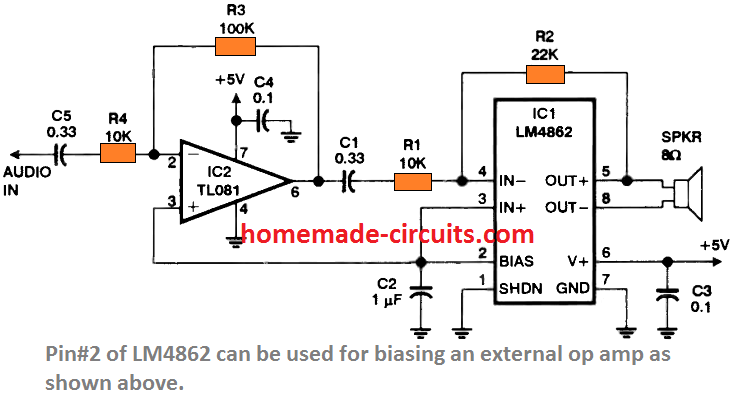
It may be necessary to bypass the bias pin to ground using any capacitor from 0.1 and 10 µF for improving ripple rejection response and also to suppress the "thump" sound each time the amplifier is switched on.
LM4862 Application Circuits
This little amplifier circuit can be actually used for all applications that require a small audio signal to be amplified to a reasonably high audible level.
AM Radio
A radio receiver circuit is one of these examples, as shown below using a tiny ZN414 AM receiver. Nevertheless, you can use the section of LM4862 stage after the R3 volume control for any similar small audio amplification purpose.
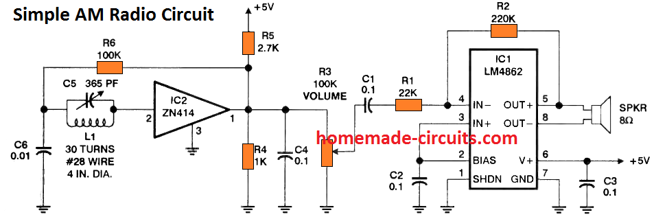
This simple radio will receive all the local AM stations loud and clear over the attached loudspeaker
Square Wave Oscillator
The IC can be also effectively applied as a simple square wave oscillator circuit as shown below:
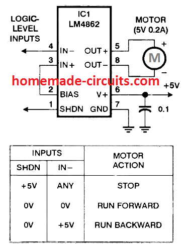
Bidirectional Motor Control
Although the IC LM4862 is designed to work like an audio amplifier it can well be applied as a full bridge motor driver stage, and the direction of the motor can be changed simply by changing the input logic signals, as demonstrated in the following diagram.
Reference: http://www.ti.com/lit/ds/symlink/lm4862.pdf


Questions & Answers
I got the oscillator circuit to work. But, not the amplifier. Nothing but VERY low-volume, sucky, squeaky, glitchy sounds.
Did you decide this was a better chip than the LM386 because you built an amplifier with it and got it to work??? Or just by comparing datasheets?
I have tested a ready-made unit and I found its performance to be very good. Make sure your IC is original, because the market is full of fake versions.
Well, I don’t know how to find out if Mouser is selling ‘fake’ chips. I bought 2 of them, and if I recall correctly, I did not buy the lowest price ones that they had listed on their site. And I couldn’t get either one to work as an amplifier. But, I ddid get the oscillator circuit to work.
Just a reminder: An amp should always have a volume control and most of us want to know how to change the frequency of an oscillator, so it would be helpful if you could point out—for newbies and the still almost clueless—where a pot might go in both circuits. I think I stuck a pot in for R2 in both circuits. But, I usually think a pot should be in series with a cap, for frequency control, so it was a big question for me, where to try it in the oscillator circuit.
And BTW, thanks for your site and your quick reply!
If you have purchased it from mouser then it cannot be fake, and the same is true for the IC functioning, if it’s configured correctly it will amplify sound, just like an LM386 IC.
for the oscillator circuit, I guess R1 and C1 are the frequency determining components.
For the volume control, it should be always at the input side, after the blocking capacitor.
Please refer to the Simple AM Radio Circuit, it shows how to wire the volume control.
Thank you for your honest feedback.
I just tried the amplifier circuit again. I put a 100K trimpot between C1 & R1. Is that correct? I tried a 1uF and then went up to a 100uF cap for C2. I put C4 in (22 pF). I get sound out of my speaker, but it’s whisper-quiet. Lots of clicking, too. But, that may have to do with the breadboard.
I’m testing it at the end of a chain of circuits that the little munchkin amp I built with a JRC386BD IC handles quite well.
(I’ve been working on trying to duplicate the sound of bagpipes electronically.)
You can take a look at my latest build/schematics here:
https://www.homemade-circuits.com/wp-content/uploads/2024/03/2nd-Device-Mostly-Schematics-2-Mod-Boards_compressed.pdf
And hear a recent audio clip here:
https://www.homemade-circuits.com/wp-content/uploads/2024/03/Latest-‘Bagpipe-sound.mp3
So, I’m not a total slouch when it comes to electronics (at least not when it comes to reading a schematic) and building stuff. I can make mistakes, like anyone, but I generally find them. Or eventually figure out what I’m doing wrong…
This is actually the second time I’ve worked with a BTL chip and thought it made a useless or sucky amp. If you download my schematics from the link above, you’ll see I used a similar chip in a mod circuit inspired by “Dead Easy Dirt.” But, as an amp, forget it!
All the best!
Thank you for sharing the files, the bagpiper sound simulation is indeed quite impressive.
However, as far as the IC LM4862 is concerned, it is a standard international IC, manufactured by reputed companies, so, if the datasheet it can generate a 700 mW amplified sound output, that cannot be wrong. 700mW might not be too big, but certainly audible to a naked ear.
So, the chip has to work.
I am also sure that you might not have made any connection errors because the circuit is too small for any error.
So, finally you can give it one last try, by building it on a perfboard (by soldering), because breadboard connections can be sometimes confusing or might have loose connections.
Thanks for the feedback on my audio clip and your confidence in my building skills, Swagatam! Yes, soldering the circuit might help. But, I think I’ll just leave the chips in my toolkit for now. As I said, I did get the oscillator circuit to work, and since I’ve been playing with audio circuits, it’s always nice to have another simple way to build an oscillator, besides using the 555 timer IC.
Again, thanks very much for your site! I’ve been trying to learn a bit about electronics for 3 years now (beyond the simple connect-the-dots of reading a circuit diagram, which I learned when I was a kid), and I’ve been endlessly thankful for all the generous help out there. All the people who share knowledge and circuits for free!
You are most welcome JB,
Yes, an oscillator can be built in many different ways, even by using just a couple of transistors or a single UJT.
If you have further questions or doubts regarding any circuit concept, please feel free to ask, I am always happy to help.
Swagatam, apologies, but I’ve been sharing my work for free, as well. And I just revised the PDF file I offered up above, because I realized I had not put my name on it.
Here’s the new link: https://www.homemade-circuits.com/wp-content/uploads/2024/03/2nd-Device-Mostly-Schematics-2-Mod-Boards_compressed.pdf
If you feel like links to my work don’t belong on your site, feel free to delete. Or feel free to edit my reply above and insert the new link. I just didn’t want someone to google “bagpipe,” find the link, and be frustrated that it doesn’t work.
No problem JB,
I have replaced the mediafire link with homemade-circuits link, with your name on it. I prefer the content to be published with my site name. I hope you will not mind it.
You can check it for your confirmation.
In using this chip to drive an 8 ohm speaker, I’m having trouble powering with Nickle Metal Hydride batteries in a single supple circuit configuration. When this chip is connected to an 8 ohm load it draws enough current to cause supply voltage fluctuations that I’m wrestling with curing. I am using an Mpc601 with a gain of 100 driven by a microphone which feeds into this chip configured with gain of 2, driving the 8 ohm speaker. Any suggestions/thoughts would be most welcome. I do not have the suggested 100uf next to the v+ pin yet. I’ll try that today.
Is your battery rated at 9 V or at least above 5 V?
You can try increasing the value of C2 to 1000 uF and check the response. C2 is important since it helps to keep the DC supply stabilized.
Also ensure that the volume control is held at a reasonable position and is not too high.
I cannot see any 100uF capacitor in the first diagram?
is it better? waiting for miracle.
LM386 looks nice if you don’t measure anything. The drawbacks are
– very low common mode voltage suppression (Vcc)
– harmonic distortion
– shape distortion
– oscillation during the +peak
– background chip hum
– detects cellphone radiation, clicking
– during startup and shutdown, it kicks out 3V pulses to the speaker
– instability in inverting or none-inverting config.
– many fake LM386s are on the market, with quite different parameters. Throw it into the garbage.
Look at the internal guts of LM386. The output driver with Darlington is pain in the a**. If you use transistor output driver with AB class bias 10-20mA and a decent OPAmp, it will work. Miracle chips do not exist. The LM386 is screwed up. A discrete solution is always better.
There is hope! There is an idea to use this amplifier with BT module. Can you provide such a scheme?
The datasheet does not provide a differential input circuit. The structural diagram shows only the artificial phase shifter inside.
Thanks.
You can disconnect the second input from the pin2 and use it for the differential input
Hello
It is possible to use this chip using a differential input and a differential output (additional conditions: minimum gain – up to 6 dB, load – 600ohm headphones.)
Yes, that’s possible…