The ISD1820 is a voice IC that lets us record voice from a mic and play it back using simple buttons or microcontroller. We can record between 8 to 20 seconds which depends on how we set it.
This IC is used in small voice projects, talking toys, greeting circuits, voice alerts, and more.
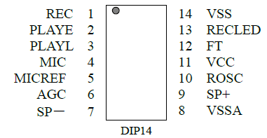
ISD1820 Pinout
Recording Time and Quality (Based on ROSC Resistor)
| Resistor Value (ROSC) | Recording Time | Sampling Rate | Audio Quality |
|---|---|---|---|
| 80kΩ | 8 seconds | 8.0kHz | 3.4kHz |
| 100kΩ | 10 seconds | 6.4kHz | 2.6kHz |
| 120kΩ | 12 seconds | 5.3kHz | 2.3kHz |
| 160kΩ | 16 seconds | 4.0kHz | 1.7kHz |
| 200kΩ | 20 seconds | 3.2kHz | 1.3kHz |
So the larger the resistor, the longer the record time, but then sound quality goes down.
Pin Descriptions (in crude simple way)
- VCC → Connect 3V to 5V power supply here.
- VSSA / VSSD → Ground pins for analog and digital parts.
- REC → When this pin goes high (like pressing a button), then recording starts. It stops when REC goes low or memory becomes full.
- PLAYE (Edge Trigger) → If this pin gets a rising signal (like button press), then it plays the whole message once.
- PLAYL (Level Trigger) → It plays only when this pin is high. So press and hold = play, release = stop.
- /RECLED → Goes LOW when recording. Can connect to LED to show recording. It also gives a pulse at end of playback.
- MIC → Connects to external microphone (goes to internal amplifier).
- MICREF → Reference pin for MIC. Helps cancel noise.
- AGC → Automatic Gain Control. Use capacitor (like 4.7uF) here to adjust voice volume handling.
- SP+ / SP- → Connect directly to 8Ω speaker. Works like mono speaker output.
- ROSC → Connect resistor here to control recording time.
- FT (Feed Through) → When this pin is HIGH, then voice from mic goes straight to speaker (like loudspeaker/megaphone mode).
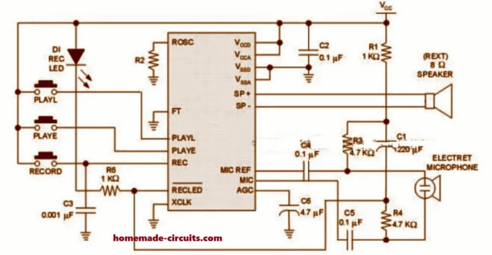
Circuit Diagram
How to Use – Step by Step
To Record:
- Press and hold REC button.
- The LED connected to /RECLED will light up.
- Speak into mic.
- Release button to stop recording.
To Play:
- Press PLAYE once → message plays completely.
- Press and hold PLAYL → plays only while button is held.
To Loop the Message:
- Connect a switch to loop mode circuit.
- Press PLAYE, then message keeps repeating.
- Only way to stop = turn off power.
Feedthrough Mode (Live Mic to Speaker)
- Make FT pin HIGH.
- Keep REC, PLAYE, PLAYL all LOW.
- Now mic will send sound directly to speaker, like a megaphone.
- Sound is clean and auto-adjusted by AGC, does not distort easily.
Tips:
- If you want super low power then you can wire mic circuit so it only gets power during recording.
- For stronger sound you can add external amplifier like LM386, TA7368, D2822, etc.
- Signal comes out from SP+ or SP- through a capacitor.
- The unused speaker pin must be left unconnected, not grounded.
Applications:
- Can be used for door greeting, talking toys, alarms, reminder boxes.
- Easy to connect with Arduino or microcontroller.
- Best to use 5V regulated power for stable voice quality.

Questions & Answers
Hi,
What I forgot to tell you is that you’re right about the mark hole. I didn’t notice it untill I took an image of the module and after zooming in. My eyes get worse nowadays. It seems to me that all components get smaller and smaller. I’m in that age that in earlier days, radio and television had to warm up few minutes before you could enjoy them. I’m from 1955.
Keep up the good work and enjoy your hobby,bye
Yep, that can happen to all of us…with age our system starts getting less and less efficient…God bless you too, and have a great festive season!
First of all I want to thank ÿou for taking the time for my problem and confirming that it’s not the ISD1820. In my opinion it’s neither the ISD1600 cause the pinout is also different from mine. Anyway it’s not so important anymore cause the main reason was to connect the module to a line-out. I found a solution by using a transformer on the place of the microphone which was used in a electric fly swatter😂😂. The line output is much too high to connect it to the module. First I tried it by attenuation but there was too much distorsion and noise. Now it works perfectly by means of the transformer. I can now download any sound from my phone without any distorsion.
By the way, the module let me download 50 seconds in stead of 10 sec without changing components. What aliexpress is saying is not always the truth.
Thanks again for your help and may God bless you and maybe till next time. And remember Santa comes from Finland, maybe he drops a present for you.
Best regards,
Koos Coolen,
Myrskylä,
Finland
No problem at all, Glad to know the problem is solved now….. so now you can download any sound from your phone crystal clear!! sounds great!
Hi,
I have a ISD1820 module and on it is a smd circuit with 16 pins. I have tried to get the pinout of that IC but I cannot find it at all. I measured some pins but I don’t know if the position is right cause there is no “hole mark” in it.
pin 1 = play
pin 2 = record
pin 3 = ?????
pin 4 = speaker
pin 5 = speaker
pin 6 = ground
pin 7 = Vcc
pin 8 till 15 unknown
pin 16 = play loop
I would be very grateful if you could help me.
Sincerely,
Koos Coolen,
Myskylä,
Finland
Hi, as per the pinout details of the IC, as shown in the above article, pin#1 goes to the record button, pin#2 goes to the PLAYE button, Pin#3 to PLAYL button, and so on, so your assumption might not be correct. Here’s the compete circuit diagram of this module for your reference:

Hi, thanks for your quick reply. it’s hard to believe but my circuit has 16 pins in stead of 14. Also Im sure that the pinout diagram is different from the one you told me about. I will try to send you a picture of the circuit board separately from this email cause I don’t see an option to make an attachment to this mail. I reallly measured that record button is connected to pin 2 (supposing that the circuit is in the right position) and it’s really obvious in the photo that it’s connected to pin 2 as you can see. Also the other pinouts differ from the one you sent me. I wonder if this circuit is really the ISD1820 I also try to send you the schematic of it as far I could discover. Don’t pay attention to the microphone cause I’m doing some experiments to connect it to a line-out output. That’s why I have to know what pin is the AGC (automatic gain control).
I don’t know where to find the datasheet of the ISD1820 if it is really the component they pretend to be. Hope you can help me.
It looks like the IC is not the ISD1820, rather it is the ISD1600, and from your sent image the black spot on the IC can be clearly identified, which indicates the pin#1 or the start of the IC pinouts. Yes, REC button goes to pin#2.

Let me know if you still have any doubts regarding the pinouts.