A plug-in type powerful wall LED lamp can be built at home by using a few white LEDs and by powering it through a cell phone charger. The power from cell phone charger is around 6 volts at 500 mA approximately.
Why use a Cell Phone Charger
The supply from a cell phone charger may be well suited and can be tried for powering white LED lights. The application includes some important types like a LED tube light circuit, LED wall lamp circuit, LED porch light, LED table lamp etc. to name a few.
A discarded, spare cell phone charger and a few inexpensive LEDs are all that you want you make a simple yet powerful LED tube light. The cell phone charger can also be used for making a porch light, a bed room wall light or a table lamp. Full circuit schematic is enclosed here in.
A nice little wall mounted cool LED tube lamp circuit can be built using a few number of white LEDs and s discarded AC mobile charger adapter.
The use of a cell phone charger makes the entire unit very compact and perfectly mountable on wall sockets.
Cell phone chargers are not new to us and nowadays we all seem to have a couple of in spare with us.
This may be mainly due to the reason that whenever a new cell phone is procured a charger comes free within the package with the handset.
These units are so long-lasting and rugged that most of the time chargers last more than the cell phones.
These spare cell phone chargers often lie idle and at some point of time we tend to dispose them off or simply discard them from our house.
For a lay man these units may be a piece of junk, but a technical individual might make a complete gem out of it.
Especially a person who may be an electronic hobbyist will very well know how valuable a cell phone charger can be even when it’s not being used for its actual intended purpose.
What are Cell Phone Chargers and How do they Function
We all have seen a cell phone charger working or rather being used for charging cell phones. Therefore we definitely know that it’s something to do with the supplying of some sort of power output.
That’s correct, these are actually a form of AC to DC adapters, however they are incredibly efficient as compared to an ordinary adapter which may employ a transformer for the required conversions.
Cell phone chargers are able to provide a nice six volts at a massive 800 mA of current. That’s quite big considering the size and the weight of these units.
Basically a cell phone charger is a high-grade SMPS power supply at the above rated level. Fortunately a white LED also works at potentials which quite matches with the above specs.
This prompted me to think of using a spare cell phone charger to be used as a plug-in type wall lamp.
Mind you one charger can provide enough power to support at least 30 odd numbers of high power high-efficiency white LEDs.
It simply means that the lights can be used as a compact LED tube light which can comfortably replace a common CFL light and generate light quite as good.
At no loads, a cell phone charger may provide outputs up to 10 volts, which can easily power a couple of LEDs in series.
The series will consume a minimum of 20 mA, however since the charger can supply a good 500 ma plus current we can add 15 more such series in parallel, making the total accommodation close to 30 or more LEDs.
Parts Required for the proposed cell phone charger LED tube light circuit
You will require the following parts for constructing the proposed project:
- Series Resistors - All 68 Ohms, 1/4 Watt
- An ordinary spare cell phone charger – 1no.
- White LEDs – 30 nos. for making a small tube light or 10 LEDs for making a wall mounted bedroom lamp etc. (see text)
- PCB – General purpose type or as per the project specifications.
Construction Clues
Constructing this LED wall lamp using cellphone charger is not difficult as it only requires the LEDs to be fixed in rows and columns correctly as shown in the diagram.
You may use the power from the cell phone to light any number if LEDs depending upon the requirement.
For example if you want to make a porch light for illuminating your house veranda, then probably you would need to assemble not more than 6 LEDs.
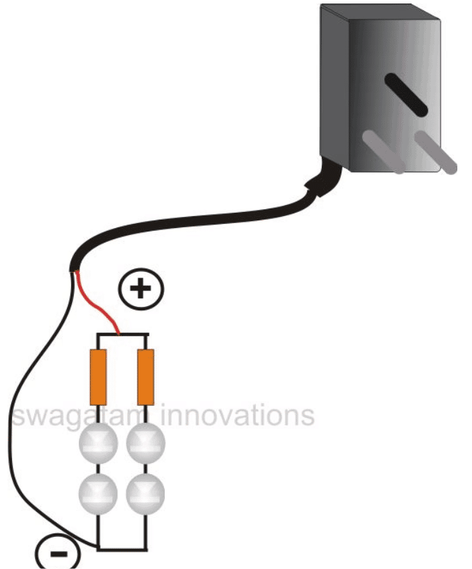
Making a Bedroom LED Light
For making a cool bedroom room lamp a single LED would suffice, instead of sitting in complete darkness, this light may be used or switched ON while watching TVs or videos.
For making a table lamp for reading purposes, a group of 10 LEDs would provide enough light for the purpose.
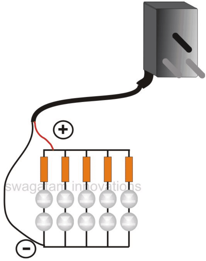
And as discussed above, a descent LED tube light can also be built by assembling some 30 + LEDs in conjunction with a cell phone charger power supply.
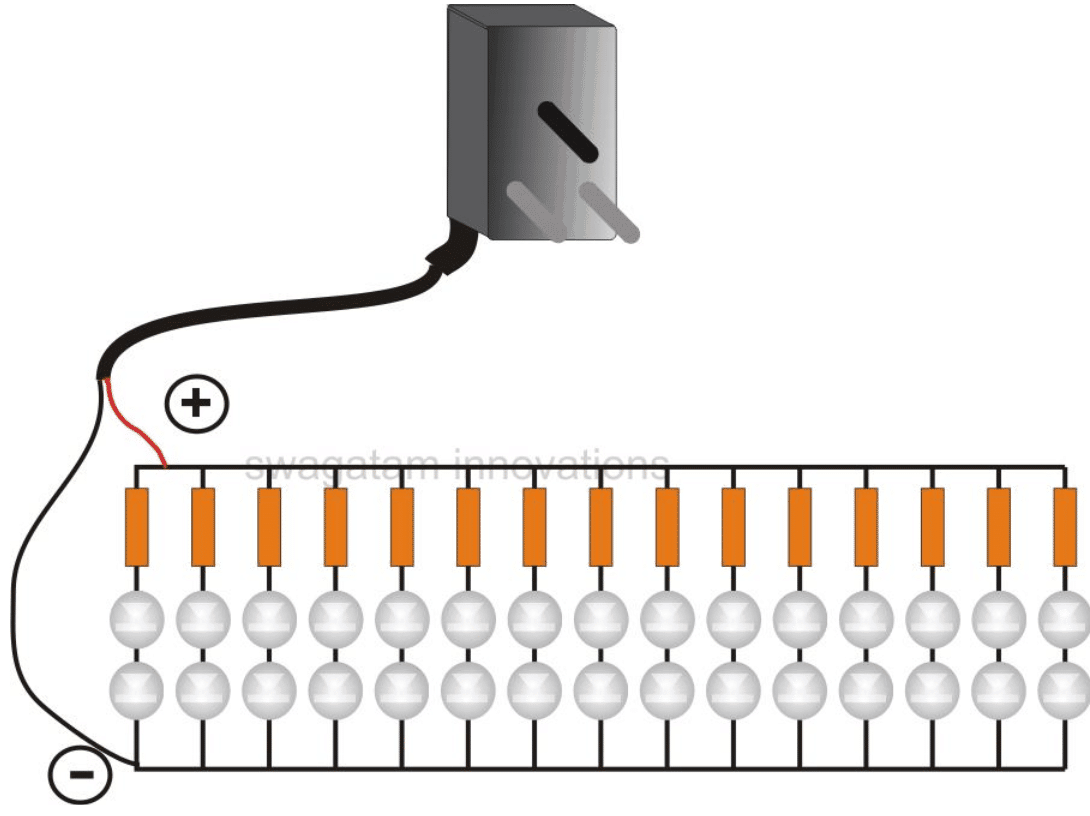
How to Solder the LEDs
For all the above applications, the basic mode of soldering and fixing the LEDs remains the same.
Fix and solder a series of two LEDs with a series current limiting resistor and now go on repeating this series as many times as you want, depending upon the type of lamp you are trying to build.
Once you finish assembling this layout, you may go joining all the free ends of the resistors which becomes one of the supply terminals, similarly join all the remaining free ends of the LEDs, which becomes the other supply terminal of the unit.
These supply inputs now just needs to be connected with the cell phone charger supply.
The LEDs should immediately come ON and produce illumination just as desired by you.
The assembly now needs to be housed appropriately inside a suitable plastic enclosure as per individual specification and liking.
A Simpler Design
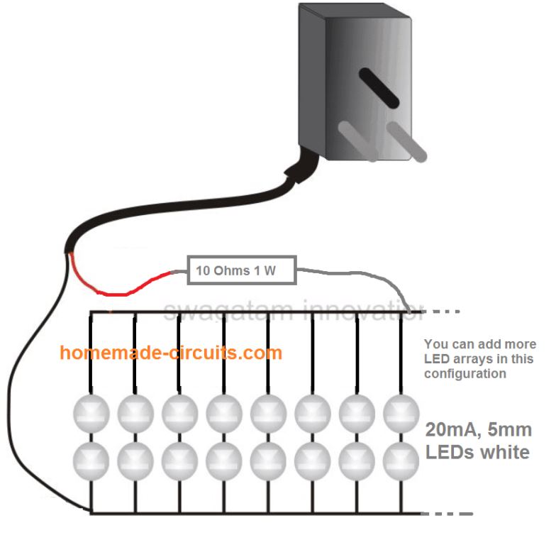
A much simpler configuration can be seen below:
Since the optimal voltage/current from a standard charger is around 8V / 1 amp, having 2 LEDs in series, we can connect 61 of such series in parallel to get 8 watt output


Questions & Answers
Dear Sir, I have a 6v AC dynamo on my bicycle. And want to replace the ordinary light comes with it with LED lights. Please let me know whether i can lit up LEDs with that DYNAMO.
Dear Narendra,
Yes you can do it. Just measure the maximum possible voltage from the dynamo and calculate the LEDs and series resistor accordingly.
R = Dyn. voltage – 3.3xno of LEDs divided by LED current (20mA for 5mm)
You can try the circuits give in the following link:
https://www.homemade-circuits.com/2012/11/making-40-watt-led-emergency-tubelight.html
how many led can connect to nokia charger with out resistors
measure its voltage and divide it with 3.3, you'll get the answer.
Hi sir its Preetam
if it's possible to do rechargeable tube using 20 LED and Nokia Battery
plz guide me how to do & what are the extra components needed.
Hi Preetam,
You can try the following circuit, use 20nos of 5mm/20ma LEds in the circuit.
https://www.homemade-circuits.com/2013/03/simplest-automatic-led-solar-light.html
the solar DC input can be replaced with a mains operated 5V Dc source
Hi,
I 've got a spare 9v 1.2A adaptor, so how many 1W leds can i connect without resistors? In series or parellel?
Thanks,
three in series.
I want to try all of this projects
Hi Swagatam, i have 33 LED's connected in series (from my old charger light) can i connect directly without resistor with my mobile charger of 5V – 500mA output.
Hi Bashab, 33 leds would require 33 x 3.3 = 109 volts to illuminate, so it won't work, you will need to connect them as instructed in the above article.
Bro ,very informative blog thanks 🙂 pls carry on
welcome bro!
i want to open a mini shop on led light plates, decoratice lights , where i get this material
electronic spare part shop
Dear Swagatam, Since I a fresher in this I have some small doubt please help…
I want to make a small tubelight of 10-15 LED with normal samsung charger… what resistor i have to use and what is the circuit diagram, I mean how i have to connect LED & resistor with charger.
with 1Watt LED & with small regular LED.
anshulg22@gmail.com
Thanks in advance.
Dear Anshul,
With 5mm LEDs, you can try the second circuit shown above, and for illuminating a 1 watt LEd you could proceed as per the following instruction:
https://www.homemade-circuits.com/2012/11/making-powerful-1-watt-led-driver-using.html
use a 6 ohm 1 watt resistor instead of 22 ohm as shown in the above link.
Hie..i wanna know that what resistor should i apply to a series of 3 leds (8mm helmet led) bulb,the supply is 12v using LM7812 ic
you can use the following formula to find it:
Supply voltage minus LED's total forward voltage drop divided by LED amp.
that is 12 – 9.9 divided by LED current
or 2.1/LED current
Sir i want to run 40 nos 1 w HLED what shoud be its design if run on 220 v ac
Deb, see the last example in the above article you will need a similar configuration, but connect 3 LEDs on each string instead of 2 and use 6 ohm resistor on each string. Also with 39 LEDs you would be able to get only 13 such strings in parallel.
now as shown in the diagram connect the assembly with a 12V 2amp smps adapter for illuminating the whole array of LEDs.
make sure you use sufficient heatsink for the LED assembly.
i have a spare laptop charger cani use it ???
please check and specify the output voltage, the LED series specs will change depending on it?
dear sir
if i use 12volt battary and 3volt high bright LEDs (20/30nos) instead of cellphone charger. then what should changes i make in this circuit?
dear Aarya,
what is the amp rating of the LEDs? make strings of three in series with a series resistor, make 10 such strings and put all these strings in parallel across the battery terminals.
for 1 watt LEDs use 6 ohm 1 watt resistor on each string, for 5mm 20mA LEDs use 150 ohm 1/4 watt for each of the resistors in the series.
Very nice..indeed
thank you!
thanx a lot. Sir!
well, yeah you doing good job.
thank you Dev!
Sir i'm here again wit trouble…..
Actually i bought some 12volt 10mm 20mA LEDs light some days ago. In that light two LEDs strings connected in series and another one LED strings connected with 10 Ohms resistor in series with other two LEDs. There are 24 such LEDs in circuit. Now Days some LEDs getting dimmer and dimmer. i can't fix it myself so i need your guidence Sir! please help me.
By the way there power sorce is Solar battary charging system. if you have diagram circuit for 10mm, 20mA LEDs using 12V DC please suggest me…………….Thanx
Dev, with a 12V supply for 20mA LEDs you should use 3 in series with a 100 ohm resistor.
Hi sir..
I have Samsung charger with 9volt & 0.6 A out put
Suggest me which led should I use 5 mm or 1w high power..?
and how many number with proper value of resister. .?
Want maximum nom of led to use
which is better 5mm or 1w.?
thanks
Hi Chirag, if you want to use 5mm leds you may go ahead and wire them up as per the given diagrams in the above article, the part numbers are provided in the article itself.
If you intend to use 1 watt LEDs you may do so by connecting a couple of them in series along with a 8 ohm, 2 watt resistor, the LEDs will need adequate heatsinking for optimal performance.
Use rectification and filter capacitor parlay
i have a nokia charger n i want 2 connect 10 leds in series can i do it without a resistor
10 leds cannot be connected in series since the charger voltage is only 5V.
sir i have a 6 volts at 100 mA……..how many series i can use………??
you can use 2 LEDs in series and two such series in parallel, as shown in the first diagram above.
i have a 9 volts at 500 mA charger……….how many 1 watt led i can use……….????
you can put three 1 watt LeDs in series, without any resistor.
use sufficient heatsink
Hello Sir, i am big fan of your work, i want to know something with this article.
I have 1w high bright round led. and i have old phone charger output is 5v 800ma/1a.
i seen that if we put more then 3v to 3v led, the led get hot instantly, so what resistor i can add to single led to glow my led???? actully i want to build 30w led tube light (30led x 1w = 30w) in 4ft scale (all LED in parallel). so i want to know what value resister i need to add to each led???
I am waiting for ur reply, Thnk you 🙂
Hello Sir, i am big fan of your work, i want to know something with this article.
I have 1w high bright round led. and i have old phone charger output is 5v 800ma/1a.
i seen that if we put more then 3v to 3v led, the led get hot instantly, so what resistor i can add to single led to glow my led???? actully i want to build 30w led tube light (30led x 1w = 30w) in 4ft scale (all LED in parallel). so i want to know what value resister i need to add to each led???
I am waiting for ur reply, Thnk you 🙂
Thanks Kamlesh,
you can illuminate only two 1 watt LEDs from a cell phone charger, you can use a 6 ohm 2watt resistor in series with it.
put two LEDs in series and also connect the above mentioned resistor in series with it.
for making a 30 watt LED tube you may need a 2 amp, 12v SMPS adapter
….sorry not 2 amp…it should be 3 amp
Thank you Friend,
Thx for the reply, 🙂
I am sorry but my charger output is 5v 800mah and I did connect 2 led in series but its not glow, its need minimum 6v…..( led need minimum 6v to glow)
actually I did another method, I did1w 30 led in parallel so the only watt increased to 30w and led need minimum3v, so I did with diode 1n4007 I know this diode reduce 0.6v, I did like this
input 5v – 3 diode 1.8v = I got 3.2v output, I connect 30 1w led in parallel and its worked fine.
I want to ask you if any resistor I need to attach ????
because I run my method for 2 hrs only and worked fine, nothing got heat,
please suggest me best way. Thank you.
Hi Kamlesh, many chargers produce 6 to 7V at the output, therefore I suggested to use two LEDs in series.
if you connect 30 LEDs in parallel, each would run at around 130 mA…that;s far below the 350mA actual rating of the LEds…so the total output would be around just 0.13 x 30 = 4 watts
if it's not heating that indicates that it's not working at the specified power rating:)
ok, I will use another charger, thank you very much.
Ok. can I use 66ohm resistor by doing 22ohm resister in series??? ex: 22ohmx3=66ohm..??????
because I have 100's of 22ohm brand new resistor.
Hi friend,
I am sorry but I don't know what happening here with me, I did as per you shown in diagram with part list,
1w led 2ps in series and with each series i connected with 68ohm resistor, total 15 series.
and the result is= very very very dim brightness ( my radium sticker brighter than this led brightness)
so after much thinking i did one,>>>>
1w led 10pcs (round led)
10ohm resistor 1pcs ( 10ohm and i forgot that it was 1w or 2w)
1 old Sonyericsson charger (mentioned output 4.9v 500ma)
ok what i did i will tell you.
i connected all 10 led's in parallel.
i connected 10ohm resistor one point in positive (+) side of charger and another point connect with positive (+) side of led, and led's negative (-) side connect with charger negative (-) side.
i plugged in the charger in mains.
result:-
good brightness…………… 🙂
my room is 10×12 sqf and this is enough brightness.
result of parts after continues run 3hs :-
led = not heat (its normal)
resistor = normal heat (not much heat, its normal heat)..
Please tell me its ok?????????
Thank you,
the shown diagram is for 5mm 20mA LEDs….it's not for 1 watt LEDs.
if you connect 30 LEDs in parallel, each would run at around 130 mA…that;s far below the 350mA actual rating of the LEds…so the total output would be around just 0.13 x 30 = 4 watts
if it's not heating that indicates that it's not working at the specified power rating:)
Hello sir I want to run 100nos 8mm white leds in parallel ……..led have 3.3 v 0.2ma …..is their any smps for that which glow bright and work for a long period
Hello Abdul, 100 in parallel would require 20 amps at 5 V which doesn’t appear to be a workable configuration. Instead you can use 4 LEDs in series and connect 25 such series in parallel, which would then require a manageable 12V 5 amp.
i have 1 amp charger and 40 led 1 watt how to arrange plz tell me
with 1 amp 12V only 3 LEDs can be illumunated
ok thanks sir
Sir namaste i have 1 watt led diode bulb how many led connected with 5v 500mah charger without heatsink plz help me thank i m wating for ur reply
Swagtam sir i have 1 watt led if i connectd that is very shining but very heat up when i use 68 ohm resistors light so dim which resistr use and how many led allow to connected thanks sir
Sandeep, try two in series without any resistor….if still it gets hot then you can add a 10 ohm resistor to reduce the heat.
Sir how much power does your ckt comsumes
Sir mobile charger may consume 3-7watt when its connected to mobile
But if led is connect then whats the power consumption
Punith, it will depend on the LED spec and the resistor calculated for limiting the current for the LED
Ok sir lets take 1w led and no resistor
Teach me to calculate the power consumption
Punith, you can use the following formula for calculating the resistor
R = (supply voltage VS – LED forward voltage VF) / LED current
I want to learn more could u give me u r mail id pls
you can ask your questions here, through comments….
Sir if i connect a nozzle to water pump outlet does it affects the efficiency of motor or does it damage the motor parts
This is not a circuit related question, so I have no idea about it.
Sir suppose 100 LEDs are connected in series ( +-+-+-………..-) now i need to transmit a bit ( say 1, high state ) through these leds.. so this will look like a collision transfer between succeeding atoms in a substance.. so could u please suggest a method by which i can implement this ? not using several decade counters but with a single ic or logic setup ?
RT, I am not very sure how a bit could be passed through a series of LEDs, however one thing can be assumed, that since the bit is also a voltage pulse its potential must be higher than the total forward drop of the LEDs, otherwise the "bit" might fail to reach the other end of the series.
that is ok.. but if i am giving a voltage more than the total voltage drop, all the leds will glow together, not one after the other.. then how the cheap led light systems available in market works in such a manner that one arrow shaped led bunch travells from one place to an another .. without using many electronic components and dealing with 100s or 1000s of LEDs ?.. i am pretty sure a bunch of decade counter ics ( say CD4026 )is not a solution for these types of led arrays is there anything to be done with ceramic capacitors in these ?
LEDs can NEVER illuminate in a sequencing manner without an IC processor…..definitely it will require decade counters, it doesn't need to be in the form of 4022 of 4017, it could be in the form of embedded programmed micro chips, as normally used in all cheap Chinese ornamental LED sing lights.
k sir… got it… thank you for this usefull information
. sir one more thing can a beginner like me who is having deep interests in doing DIY electronics projects be able to use a RASPBERRY PI computer to make the result possitive as expected ? Is it good enough for doing even high grade projects ?
I need your opinion about RASPERRY PI
yes it is possible, but a prior basic knowledge of electronic component will be required….learning Arduino initially could be more beneficial.
thank you very much sir
sir
(1). in a CFL lamp circuit what is the voltage applied between the anode and cathode of the tube ( say output voltage from the circuit )
(2). What is actually happening in a cfl circuit ? is the final voltage given into the tube terminals AC or DC ?
(3). Can we make a portable inverter of less power ( say same as the CFL Power ) with that CFL circuit ?
(4). I am having an arrangement of 22 high brightness LEDs which can be directly plugged into an AC bulb holder.. I want to modify that bulb such that it should work with a rechargeable lesser voltage battery ( say 12 V or less ) .. So anyway to modify the cfl circuitry to make this possible ? collaborate the modified cfl circuit to glow my 230 V led lamp with battery ?
RT,
The mains is converted to 330V DC and then converted into a 330V pulsating DC, this DC is applied across the tube.
CFL circuit cannot be used as an inverter
you can make a standard 12V, 100 watt inverter and use it to power your LEDs
I have a 4 x 100w led chip. Would this work using diagram above? And what resistor would i need?
Would this work with 100w chip? Resistor 100w?
absolutely not…cellphone charger output is just 15 watts
hi, I am using 2, 15 W bulbs (one red and one yellow) in the night lamp which is creating heating problem …Please suggest any workaround…Can i use red LEDs and one bright bulb in a night lamp…If yes, please tell me how can i do that with an old mobile charger…
did you mount the LeD on a heatsink, because all high watt LEDs will require heatsink for proper functioning without getting damaged.
you can use a single 20mA red LED also, with a limiting resistor…whose value can be calculated by the following formula
R = supply voltage – LED forward voltage / LED max current rating.
Sir,
3 white LEDs were connected in series to a battery supply of 4.5 volts. If I want to connect it with mobile charger with 5 Volt 10A spefication, what will be value of resistor, to be connected with the circuit to get the optimum glow of LEDs.
Debasis, white LEDs are normally rated at 3.3V therefore 3 of them in series cannot light up with a 4.5V supply that’s impossible. Even with a cell phone charger you may be able to connect only 2 LEDs in series, 3 might not produce proper illumination.
With a 5V 10amp supply you could connect the 3 LeDs in parallel, and use a resistor in series with each of the LEDs. Assuming your LeDs are rated at 20mA each, the value of each resistor would be:
5 – 3.3 / .02 = 85 ohms 1/4 watt each
Many thanks for your valuable information.
you are welcome!
I am facing a unique problem, I have 1.5V pink led , if i connect it two led in series and and use 3v power supply led glows, but if i connect it with mobile usb charger it doesnot glow, i found if i connec it with mobiel powers upply voltage drop against led is 3 volt , why is this happening
?
Mobile charger output will be 5V, so most probably the LEDs are by now damaged and are creating short circuit for the charger. With a mobile charger you must connect a series resistor with the LEDs. The calculations will be like this:
R = 5 – 3 / LED current
Hi Swagatam,
I want to build a light with the help of a old Nokia mobile charger with approx 20 white led, 6 blue & 6 pink led. Kindly guide me the value of resistors to be used in this circuit.
Thanks
Hi Olo, can you please specify the current specs of the LEDs? I’ll try to help!
i would be using a 5mm led with a fwd voltage of 3.2v
Make separate series/parallel groups of white, blue, and pink LEDs. White will have 10 strings in parallel, each string having 2 LEDs in series. Blue and pink will have 3 strings in parallel, each having 2 LEDs in series.
Connect separate resistor for these groups at their positive common ends. White will have 5 ohm 1 watt, blue and pink will have 16 ohms each.
Connect the end terminals of these resistor to the positive supply, and also join the negative ends of all the groups/strings together and connect to the negative supply
Thanks Swagatam, that was really informative. Will try this and get back to you.
My Pleasure olo!
In one lamp I want 1 white led
White led 3w 3.2-3.5v 700mA
In other lamp I want 4 white led
White led 3w 3.2-3.5v 700mA
And in other lamp I want to conect 2 white 1 red and 1 blue led
White led 3w 3.2-3.5v 700mA
Blue led 3w 3.2-3.5v 700mA
Red led 3w 2.2-2.6V 700mA
Using independent power supply for eah lamp, Is it possible using a Cellphone Charger ?
If you are using separate chargers then it may be possible…
Hello Sir,
I have 42 white LED’S (each of 5mm) arranged on a single PCB (taken out from rechargeable lantern since lantern battery is dead). I have no idea about LED’S arranged in series or parallel.
and
I have Nokia charger of 5.7v and 800ma output. Can i light up that LED’S arrangement with Nokia charger ? Please guide.
Hello Anurag, if the battery of the lantern was a 4V battery then certainly the LEDs are in parallel. Alternatively you can connect the NOKIA charger through a 100 ohm resistor, if the LEDs illuminate then they are in parallel and you can continue using the charger for powering the LEDs.
Can you help me with this? I cant compute how many incandescent mini lights i will use to power it in AC 220v.
divide 220 with the incandescent lamp’s voltage rating. More info is give in the following article:
https://www.homemade-circuits.com/make-230-volts-bulb-string-lights-for/