You might have already read about this interesting idea in many different sites. It's about converting a dead CFL into a sleek LED tube light circuit. In this post I have explained the procedures with more details.
How many times did you throw away a dead or over used faulty CFL unit into the dust bin? Well, we do this quite often whenever we find one of our home CFL lamps no longer illuminating or illuminating dimly.
You would be surprised to know that the circuit inside the lamp in fact never blows of or becomes weak. It's the tube portion which gets blackened, and unresponsive. It means the circuit of most of the discarded CFL units never goes faulty, and can be recycled through some other means.
For a layman this might look pretty tough....but actually it's quite easy. The tube portion of the CFL may be simply replaced with LEDs, and reused for getting the same illumination that your previous CFL used to give... well almost the same.
I have explained the procedures.
How to Convert CFL into LED Bulb
Find a dead CFL unit, and very carefully open up the lid which holds the tube from the lower cup type enclosure.
You must do this very carefully using a screwdriver equipment, making sure you don't damage the internal circuit while doing this.
If you find it difficult to insert the screwdriver end across the joint opening, use a fine hacksaw to make a small section of the opening wider by sawing it some. Now you can force open the lid by using the screwdriver.
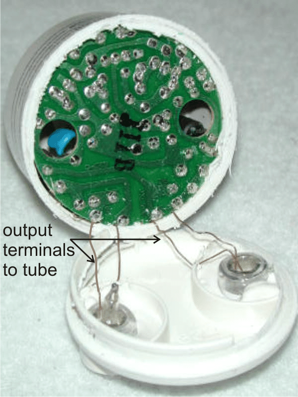
This will immediately expose the internal circuit and the connections.
You will find the tube ends terminating with a pair of wires and connecting with the circuit board at four points arranged in a row through fine wire links. Cut these connections with a sniper so that the tube portion gets separated from the circuit board.
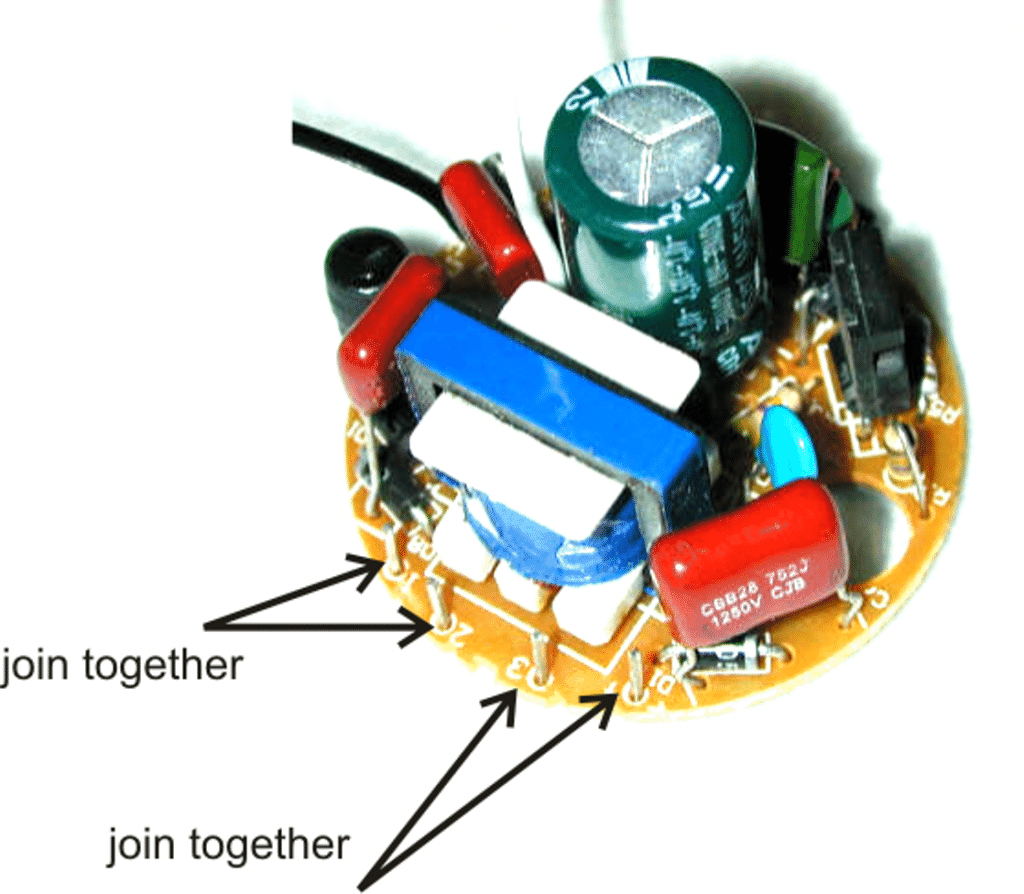
Join the above terminals from the ends so that only two terminals end up as the output.
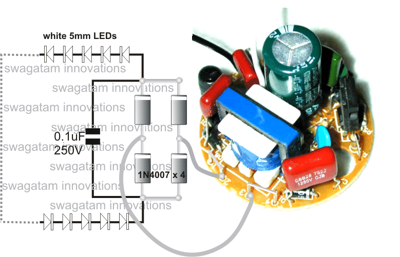
Next using 4 nos 1N4007 diodes build a bridge rectifier, and connect it to the above terminals as shown in the diagram.
Now through a suitable holder and plug device connect the above system to mains and check the voltage a the output of the above connected rectifier.
It should be around 100 to 150 volts DC.
You have just transformed a dead CFL into a small transformerless power supply ideally suitable for illuminating LEDs (white).
Now comes the LED assembly part which may be constructed in the following manner:
To figure out the number of LEDs that would fit inside the output voltage of the above unit, we need to divide the measured voltage with 3.3V. Suppose the measured voltage was 120V, dividing this by 3.3 would give around 36 (numbers).
Use the derived number of LEDs and connect all of them in series with a 5 Ohm, 1/4 watt series resistor.
Done! Now simply connect the LED assembly end terminals with the bridge output of the modified CFL power supply.
You can test the system by providing mains supply to it....the LEDs should illuminate with dazzling light.
Now fix the assembly appropriately so that the CFL circuit gets inside its original holder while the LEDs may be integrated to the holder over a suitable rectangle type of box, or inside any other decorative cabinet as per user preference.
WARNING: THE IDEA IS BASED ON A SIMILAR CIRCUIT WHICH WAS PUBLISHED IN A DIFFERENT WEBSITE, IT HAS NOT BEEN VERIFIED BY THE AUTHOR.
THE CIRCUIT IS NOT ISOLATED FROM MAINS, AND THEREFORE IS EXTREMELY DANGEROUS IN UNCOVERED, POWERED POSITION.
Another Idea
The method of converting a blown CFL into an LED lamp as explained above looks unnecessarily complex and risky. A better and a foolproof technique would be to salvage a few of the useful parts from the CFL PCB and then apply them to build a simple tranformerless LED driver.
The parts which needs to be extracted can be learned from the following explanation.
Typically, you will find a few PPC capacitors present (which look like chewing gums), check the values and pick up the one which has the highest value in terms of uF and also the voltage value.
The voltage is more important, and make sure the picked one is rated above the supply value of your home AC. So if the supply AC is 220V, the capacitor should be above 250V minimum, and likewise.
Next, remove the filter capacitor, which would be in electrolytic form, and also the 4 diodes from the bridge rectifier.
After collecting these de-soldered items, assemble them back over a separate stripboard or piece of general purpose board with the help of the following schematic:
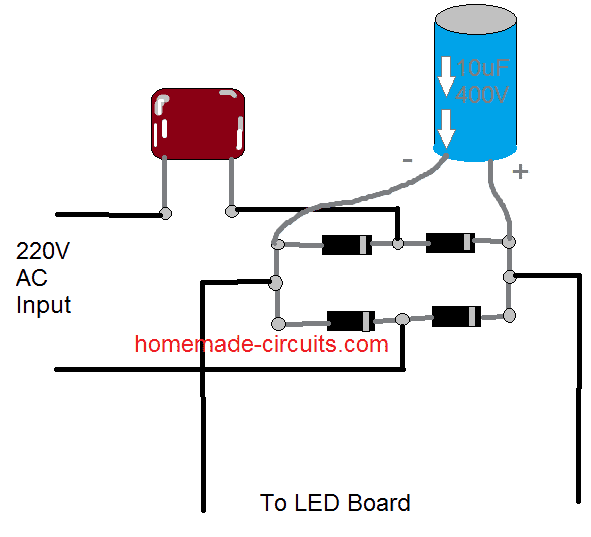
Once you have built this, the rest of the parts and the CFL PCB could be removed and thrown away, we don't need it anymore.
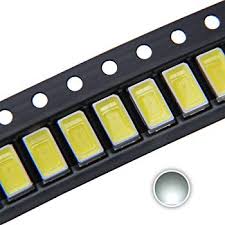
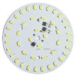
After this, procure around 50 LEDs @ 20mA , preferably SMD type as shown below, and assemble them in series over a circular PCB.
Finally connect the +/- ends of this series LED assembly with the "LED board" points of the above explained power supply circuit.
Feed the 220V input to the capacitive supply and watch the LED dazzle up with mind blowing brightness.
That's it, you have just converted a dead CFL into a high bright LED bulb. Enclose the whole thing inside the CFL box, and glue the PCB appropriately, plug it in your home bulb AC socket for the preferred use
Note: The quantity of LEDs is intentionally selected to be 50nos to get an increased brightness and also better surge control.
Remember here we are assuming the input PPC capacitor to be not more than 0.22uF. If its more than this value then you may have apply a series resistor with the LED assembly to enable an improved surge restriction.


Questions & Answers
hi dear sir do you can help me to converting cfl to power supply?
tanks in advance
hi drar sir i convert an cfl board to an power suplly i pickup capacitor hi voltag on borad and put an trafo ferit ee19 with air space in middle leg with 1mm and output 12 v but i could not control voltag in output i put an optocopler with zener diod and grounding base of 13003 where is side diac but output is bliking with 1 secound time do you have any why for my circuits
tanks in advance
Sorry sedigh, that can be very difficult to diagnose and suggest, because a CFL is deigned to generate high voltage and low current.
However if you are able to get a fluctuating 12V, then you can try adding a diode and a 1000uF capacitor at the output and see if that stops the blinking issue
tanks very much
you are a man who do not have any prid and for sharing info without cost
i appreciate for your help to all and i wish best of god
tanks and regards
You are welcome sedigh!
Oi meu caro amigo muita coisa boa para aprende, pena, eu não sei nada de inglês. Só vejo as figuras dos projetos acho interessante mas não consegui ler.
Thank you friend, you can use “Google translate” to translate the article.
hi all,
in this circuit we are shorting two points which, originally were having a filament of lamp in between them, means some resistance should be there , but if you just short them, how will it work?
I have started with a good 7 and 5 watt CFL of 20 watt CFL
इस cfl के सर्किट में आउटपुट 40v,ac आता हे diode 4007 ractifive करने पर,40 v तक ही led की series use कर सकते हे, स्वागतम सर मैने चेक किया है,led heat होती है,hestsink लगने पर भी
You are rectifying a high frequency current. It is not 50 Hz AC.
You need to use schottky diodes for rectification.
appreciate your efforts, Pleas try using a resistor in series with the LEDs, and see if that helps
Dear let me know the results that total number of leds used in ,
What's the output of a 5 watt CFL,,and anyway of converting the output from a flyback transformer driven by 5 watt CFL,,,soo do I connect 10;in4007 diodes in series and make a rectifier with 10kv standard,,,,and finally HVDC into normal 300 v using bunch of resistor and regulator and inductors
Is there any lol wat I stayed,,,or it works 100% sure sir
Waiting for ur reply
???????
the output will be 5 watts with voltage level in many hundreds of volts, because CFL tube requires high voltage to ignite. sorry can't answer the second question because I am not sure about it???may be this diagram will give you some hint ???
https://www.homemade-circuits.com/2014/03/mosquito-swatter-bat-circuit.html
SIR , by the dead CFL can i use that as an dc power supply to my circuit projects. if yes how much DC volt can i get from 15w cfl . and how can i test how much volt that i can get from different cfl's of different watt'age thank you
Manjunath, that's not possible, because CFL drivers are designed to generate high voltage and high frequency at their outputs, not suitable for DC power supply application.
Hello sir .i want 20watts led driver circuite.plz help me
hell siddh, please provide more details, what is the voltage of the LED, is it an AC to DC driver or just DC to DC driver
Thanks for the valuable and time saving reply
hello sir I am Rakshit. i am working on 20 watt clf to make tube light of 18 watt. how many voltage usage in this?
Hello Rakshit, sorry I have no idea whether that's feasible or not using any modifications
I have 20watt CFL with 400volt 8.2 micro farads capacitor.please tell me how to modify the circuit to make high voltage bug zapper. I have 4 capacitors with 400volt 2.8micro farads capacitance please help me out.
I have not yet investigated a CFL circuit thoroughly so I cannot suggest my opinions about it.
very good
thank you
i checked this and it is not working 🙁
Hello sir
I m manoj . I m working on a cfl pcb.its working fi9 but I want to add a mov for better protection. Plz suggest me a move for 15 w cfl pcb.i m using 13003 transistor.plz help me with the value of mov.
Thanks
Hello Manoj,
you may use a 300V/10amp peak MoV as shown in the following image:
hey swagatam i made this circuit my led glows for 5 minutes than without harming any led or other component just stop glowing and i figured it out in both terminals there is power showing how can i fix that problem please do reply fast
correct link:
https://www.homemade-circuits.com/2012/04/how-to-make-led-bulb-circuit.html
I am not very sure about the above design so cannot confirm, why don't you try the following design:
https://www.homemade-circuits.com/2012/04/how-to-make-led-bulb-circuit.html