The proposed electronic candle circuit does not use wax, paraffin or flame, yet the device perfectly simulates a conventional candle. Basically it incorporates ordinary electronic parts like LED and battery. The interesting part of it is that it can be extinguished with literally a puff of air.
The proposed electronic LED candle circuit helps you to get rid of the age old types of candles which use wax and fire for illuminations.
This modern candle not only produces better illumination than the conventional types, it also lasts much longer and that too very economically.
Moreover, making the project at home can be a lot of fun.
The main features of this electronic candle circuit includes, higher illumination, low consumption, automatic switch-ON facility when power fails and is extinguishable, literally by “puffing” OFF the candle.
Circuit Operation
CAUTION - THE CIRCUIT IS EXTREMELY DANGEROUS TO TOUCH WHEN OPEN AND CONNECTED TO AC MAINS, WITHOUT OBSERVING APPROPRIATE PRECAUTIONS CAN CAUSE DEATH OR PARALYSIS.
Before learning the circuit details please note that the unit functions with AC mains potential without any isolation, therefore may carry voltages at dangerous mains level, which can kill anyone.
Therefore extreme care and precaution is advised while working with the construction of this project.
The circuit functioning may be understood with the following points:
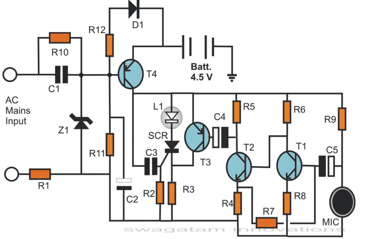
The whole circuit can be divided into three separate stages, the transformerless power supply, the LED driver and the “puff” amplifier stage.
The parts comprising C1, R10, R1 and Z1 form the basic capacitive power supply stage, which is required for keeping the circuit “aware” of the mains power availability and for keeping the LED switched OFF under the conditions.
The mains input is applied across R1 and C1. R1 makes sure that the initial surge currents don’t enter the circuit and cause damage to the vulnerable parts.
With the surge controlled through R1, C1 conducts normally and delivers the expected amount of current to the preceding zener diode section.
The zener diode clamps the positive half-cycle voltages from C1 to the specified limit (12 volts here).
For the negative half-cycles, the zener diode acts as a short and switches them to ground. This further helps to control the surge currents and keep the input to the circuit well under safe conditions.
Capacitor C2 filters the rectified DC from the zener diode so that a perfect DC becomes available to the circuit.
Resistor R10 is kept for biasing the transistor T4, however in the presence of the input power, the base is held at the positive potential and any negative from the ground is inhibited to the base of T4.
This restricts T4 from conducting and it remains switched OFF.
Since the battery is connected across the emitter if T4 and ground, it also remains cut OFF and the voltage is unable to reach the circuit.
Thus ,as long as the mains input is active, the power from the battery is kept aloof from the actual “LED candle” circuit, keeping the LED switched OFF.
In case the power fails, the positive potential at the base of T4 vanishes, so that the ground potential from R11 now gets an easy passgae to the base of T4.
T4 conducts and allows the battery voltage to reach across its collector arm.
Here, the battery voltage flows to the positive of the preceding electronic and also through C3 (only instantaneously).
However, this fractional voltage from C3 switches the SCR into conduction and latches it, even after C3 charges and inhibits any further gate current to the SCR.
The latching of the SCR illuminates the LED and keeps it switched ON for so long as the mains power is absent.
If the mains power restores, the battery is instantly cut OFF by T4, bringing the circuit back to its original position, as explained above.
The above explanation describes the power supply and the switching stage, corresponding to the presence or the absence of an AC input.
However the circuit incorporates another interesting feature of extinguishing the LED by “puffing” air, as we usually do with wax and flame type of candles.
This feature becomes available in the absence of AC mains input, with the LED illuminated. This is done by “puffing” air onto the MIC or simply by tapping it.
The momentary response from the MIC gets converted into minute electrical signals which are suitably amplified by T1, T2 and T3.
When T3 conducts, it brings the anode of the SCR to the positive potential cutting OFF the “latch” function, the SCR is immediately switched OFF and so is the LED.
Diode D1 trickle charges the battery when mains power is ON.
How to Assemble the Electronic Candle Circuit
This electronic LED candle circuit may be assembled in the usual way, by soldering the procured components over a veroboard, with the help of the given schematic.
To give the unit an impression of a candle, the LED may be hoisted over a long cylindrical plastic pipe, the circuit part will however must be enclosed inside a suitable plastic box. The pipe and the cabinet should be integrated together as shown in the diagram.
The cabinet should also be equipped with two AC plug-in type of pins so that the unit can be held fixed over an existing AC socket outlet.
The batteries may be accommodated inside the pipe. To get the required 4.5 volts, three pen light type of cell must be attached in series.
These must be chargeable types, capable of supplying 1.2 volts each.
Parts List
R1, R3 = 47 Ohms, 1Watt = 2
R4 = 1 K = 1
R5 = 3K3 = 1
R2, R6 = 10 K = 2
R7 = 47 K = 1
R8, R12 = 150 Ohms = 2
R9 = 2K2 = 1
R10 = 1 M = 1
R11 = 4K7 = 1
C1 = 1 µF, 400V = 1
C2 = 100 µF/25 V = 1
D1 = 1N4007 = 1
C3 = 1 µF = 1
C4, C5 = 22 µF/ 25 V = 2
T3, T4 = BC557 = 2
T1, T2 = BC547 = 2
SCR = Any type, 100 V, 100 mA = 1
LED = White High Bright, 5 mm = 1
Using an LDR to switch ON the Electronic candle:
The above explained design can be further enhanced such that it responds to light from a lit match stick, using an LDR as the light sensor.
The modified diagram can be viewed as shown below:
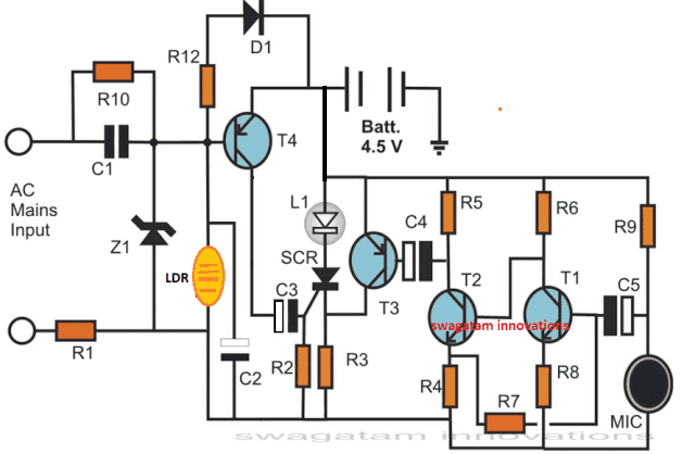
Referring to the figure we can see that the transistor biasing resistor R11 is now replaced with an LDR.
In absence of light the LDR presents a very high resistance causing the SCR to remain switched OFF.
However when an burning match stick is brought near the LDR, its resistance decreases and the transistor begins conducting, which in turn allows the SCR to get triggered and latched.

Questions & Answers
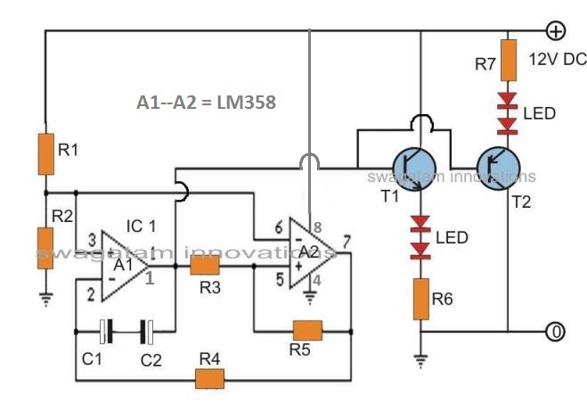
I had a small Switching circuit of C 828 and D 313 used for an Emergency Light. No relays are used for this circuit. As I can not remember this ciruit now could you please oblige me with a similar circuit diagram
You can try the following concept and modify it accordingly…
sir,
does it mean R12 and D1 will be replace with jumper or left open?
Sorry Santos, I did not understand your question.
sir
i need to operate this with battery only..what alterations are needed
remove everything that's connected with base of T4, except the LDR
waiting for ur reply…i dont want ac main supply
Thanks sir.
you are welcome..
thank u sir ….
hi Mr. swagatam, I want to do this project for my college project from where should I get the assorted components I want to know
Hi Apoorva, the components could be procured from your nearest electronic spare part dealer
Dearest Swagatam,
How might one turn it back on, without re-connecting and disconnecting it from mains power?
Dearest Tom, it can be done by adding a switch between the collector of T4 and the circuit…this switch may be momentarily switched off and then switched ON to reset the circuit
Connect an LED across collector of T3 and ground with a series 150 ohm resistor.
When you puff, this LED should light up brightly….if this is not happening means the transistor stage may be not working….
also increase R3 to 220 ohms and check the response
…the scr is OK
when i try it it just light no puff at all
i used 2n5062 scr. is this applicable to the circuit????
sir can i ask what value of mic can i used??
its either em 60 or 80
and what resistor do i need to change if my source is 6 volts???
C1 is metallized polyester, C3 is ceramic disc type
is the c1 is polyester capacitor and c3 is Mylar type of capacitor??
paolocrit,
the mic is an electret mic, see the image here:
ffden-2.phys.uaf.edu/211_fall2010.web.dir/Daniel_Randle/images/elctret.jpg
you can use the same circuit for 6V also, only C1 will need to changed to 474/400V
what do you mean by 3K3 for R3 , 2K2 for R9 and 4K7 for R11 .
sir, hello my first question is that, why 474 k polyester capacitor is used for 6volts as you mentioned above,and secondly is that the electret mic when puffed by mouth air is that mic turn on or turn off the led, and third is that you forgot to mention the value of zener diode above in the list
Hi Atul, The PPC capacitor is used to reduce the AC mains current to acceptable levels for the battery. The zener diode value can be 4.7V 1W. The MIC is used to turn OFF the LED.
3.3k, 2.2k, 4.7k