The 6 unique designs below explains us how an ordinary single IC 555 astable multivibrator could be used effectively to make an inverter without involving complex stages.
No doubt IC 555 is a versatile IC which has many applications in the electronic world. However when it comes to inverters, IC 555 becomes ideally suitable for it.
In this post we'll discuss 5 outstanding IC 555 inverter circuits, from a simple square wave variant to slightly more advanced SPWM sinewave designs, and finally a full fledged ferrite core based DC to DC pwm inverter circuit. Let's begin.
The idea was requested by Mr. ningrat_edan.
The Basic Design
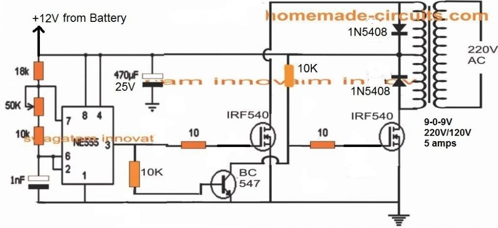
Referring to the shown diagram, a single IC 555 can be seen configured in its standard astable mode, wherein its pin#3 is used as the oscillator source for implementing the inverter function.
NOTE: Please replace the 1 nF capacitor with a 0.47 uF capacitor for optimizing 50 Hz at the output. It can be a polar or a non-polar.
How it Works
The working of this IC 555 inverter circuit can be understood with the following step wise analysis:
The IC 555 is configured in an astable multivibrator mode, which allows its pin#3 to switch a continuous high/low pulses at a particular frequency rate. This frequency rate depends on the values of the resistors and capacitor across its pin#7, Pin#6, 2 etc.
Pin#3 of the IC 555 generates the required 50 Hz or 60 Hz frequency for the MOSFETs.
As we know that the MOSFETs here are required to run alternately for enabling a push-pull oscillation on the attached transformer center tap winding.
Therefore both the MOSFET gates cannot be connected to pin#3 of the IC. If we do this both the MOSFETs would conduct simultaneously causing both the primary winding to switch together. This would cause two anti-phase signals induced at the secondary causing a short circuit of the output AC and there would be a a net zero AC at the output, and heating up of the transformer.
To avoid this situation, the two MOSFETs needs to be operated alternately in tandem.
The Function of BC547
To ensure that the MOSFETs switch alternately at 50 Hz frequency from pin#3 of the IC 555, we introduce a BC547 stage for inverting the pin#3 output across its collector.
By doing this we effcetively enable the pin#3 pulse to create opposite +/- frequencies, one at pin#3 and the other at the collector of the BC547.
With this arrangement, one MOSFET gate operate from pin#3, while the other MOSFET operates from the collector of the BC547.
This means when MOSFET at pin#3 is ON, MOSFET at the BC547 collector is OFF, and vice versa.
This effectively allows the MOSFETs to switch alternately for the required push pull switching.
How the Transformer Works
The working of the transformer in this IC 555 inverter circuit can be learned from the following explanation:
When the MOSFETs conduct alternately, the relevant half winding is supplied with the high current from the battery.
The response allows the transformer to generate a push pull switching across its center tap winding. The effect of this causes the required 50 Hz alternating current or the 220 V AC to be induced across its secondary winding
During the ON periods the respective winding store energy in the form electromagnetic energy. When the MOSFETs are switches OFF the relevant winding kicks back its stored energy on the secondary mains winding inducing the 220V or 120V cycle on the output side of the transformer.
This keeps happening alternately for the two primary winding causing an alternating 220V/120V mains voltage to develop on the secondary side.
The Importance of the Reverse Protection Diodes
This type of center tap topology has a downside. When the primary half winding throws the reverse EMF, this is also subjected on the MOSFET drain/source terminals.
This can have a devastating effect on the MOSFETs if the reverse protection diodes are not included across the primary side of the transformer. But including these diodes also means precious energy being shunted to ground, causing the inverter to work with a lower efficiency.
Technical Specifications:
- Power Output: Unlimited, can be between 100 watt to 5000 watts
- Transformer: As per preference, Wattage will be as per the Output Load wattage requirement
- Battery: 12V, and Ah rating should be 10 times more than the current selected for the transformer.
- Waveform: Square Wave
- Frequency: 50 Hz, or 60 Hz as per country code.
- Output Voltage: 220V or 120V as per country code
How to Calculate IC 555 Frequency
The frequency of IC 555 astable oscillator circuit is basically determined by an RC (resistor, capacitor) network configured across its pin#7, pin#2/6 and ground.
When IC 555 is applied as an inverter circuit, the values of these resistors and the capacitor is calculated such that the pin#3 of rthe IC produces a frequency of either around 50Hz, or 60 Hz. 50 Hz is the standard value compatible for 220V AC output while 60Hz is recommended for 120V AC outputs.
The formula for calculating the RC values in a IC 555 circuit is shown below:
F = 1.44 / (R1 + 2 x R2) C
Where F is the intended frequency output, R1 is the resistor which is connected between pin#7 and ground in the circuit, while R2 is the resistor in between pin#7 and pin#6/2 of the IC. C is the capacitor found between pin#6/2 and ground.
Remember F will be in Farads, F will be in Hertz, R will be in Ohms, and C will be in microFarads (μF)
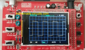
Video Clip:
Waveform Image:
Using BJT instead of MOSFETs
In the above diagram we studied a MOSFET based inverter with center tap transformer. The design made use of 4 transistor in all which appears to be a bit lengthy and less cost effective.
For hobbyists who may be interested in building a IC 555 inverter using a couple of power BJTs only will find the following circuit very useful:
UPDATE: Did you know, you could make a cool modified sine wave inverter simply by combining a IC 555 with IC 4017, see the second diagram from this article: Recommended for all dedicated inverter hobbyists
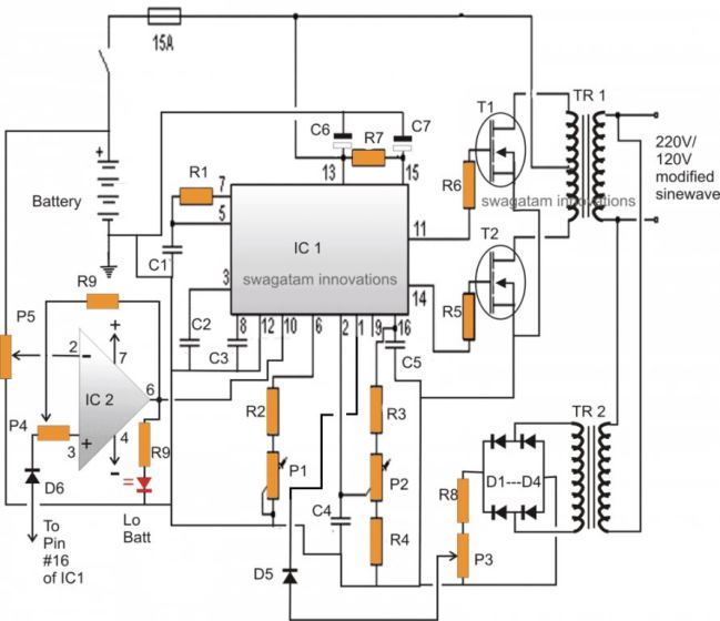
2) IC 555 Full Bridge Inverter Circuit
The idea presented belowcan be considered as the simplest IC 555 based full bridge inverter circuit which is not only simple and cheap to build but is also significantly powerful. The power of the inverter may be increased to any reasonable limits y suitably modifying the number of mosfets at the output stage.
How it Works
The circuit of a simplest full bridge power inverter explained requires a single IC 555, a couple of the mosfets and a power transformer as the top ingredients.
As shown in the figure, the IC 555 has been wired as usual in the an astable multivibrator form. The resistors R1 and R2 decides the duty cycle of the inverter.
R1 and R2 must be adjusted and calculated precisely for getting a 50% duty cycle, otherwise the inverter output may generate unequal waveform, which may lead to unbalanced AC output, dangerous for the appliances and also the mosfets will tend to dissipate unevenly giving rise to multiple issues in the circuit.
The value of the C1 must be chosen such that the output frequency comes to about 50 Hz for 220V specs and 60 Hz for 120V specs.
The mosfets can be any power mosfets, capable of handling huge currents, may be upto 10 amps or more.
Here since the operation is a full bridge type without any full bridge driver ICs, two batteries are incorporated instead of one for supplying the ground potential for the transformer and in order to make the transformer secondary winding responsive to both positive and negative cycles from the mosfet operations.
The idea has been designed by me, however it has not been yet tested practically so kindly take this issue into consideration while making it.
Assumably the inverter should be able to handle upto 200 watts of power easily with great efficiency.
The output will be a square wave type.
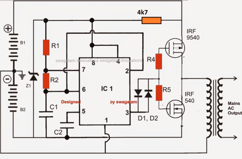
Parts List
- R1 and R2 = See Text,
- C1 = See text,
- C2 = 0.01uF
- R3 = 470 Ohms, 1 watt,
- R4, R5 = 100 Ohms,
- D1, D2 = 1N4148
- Mosfets = see text.
- Z1 = 5.1V 1 watt zener diode.
- Transformer = Asper power requirement,
- B1, B2 = two 12 volts batteries, AH will be as per preference.
- IC1 = 555
Another Full Bridge 555 Inverter
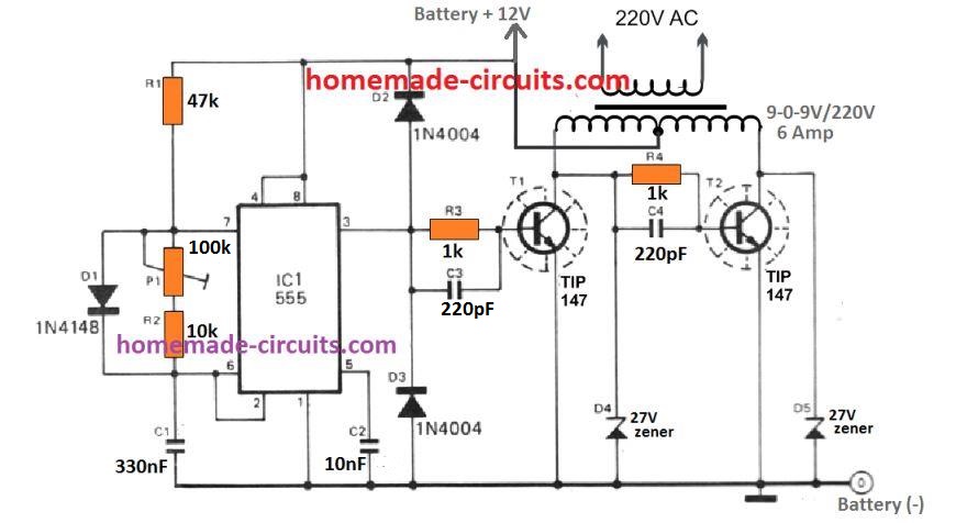
Another full bridge 555 inverter using a 2 wire transformer is shown in the following diagram. Unlike the above design this inverter does not depend on two batteries rather works with a single battery.
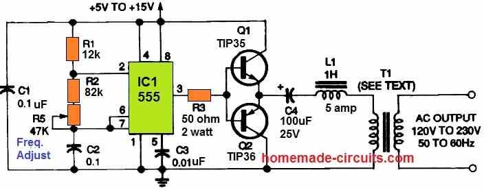
The IC 555 again is rigged as a simple astable multivibrator circuit whose output frequency can be adjusted to a precise 50 Hz or 60 Hz. The frequency is fed to push pull power transistor network using TIP35 and TIP36 configuration, which provides a high current oscillation into the connected power transformer.
A series resistor/inductor network using C4 and L1 ensure an over current protection for the transistors, and allows a controlled running of the full bridge inverter.
The transformer can any ordinary step-down transformer such as 12-0-12V/5 amp, if the supply voltage is 15V. Alternatively a 9-0-9V transformer can be also tried for a 12V battery operation.
3) Pure Sine wave SPWM IC 555 Inverter Circuit
The proposed IC 555 based pure sine wave inverter circuit generates accurately spaced PWM pulses which imitates a sine wave very closely and thus can be considered as good as its sine wave counter part design.
Here we use two stages for creating the required PWM pulses, the stage comprising the ICs 741 and the other comprising the IC 555. Let’s learn the whole concept in details.
How the Circuit Functions – The PWM Stage
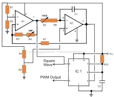
The circuit diagram can be understood with the following points:
The two opamps are basically arranged to generate the required sample source voltages for the IC 555.
The couple of outputs from this stage is responsible for the generation of square waves and triangular waves.
The second stage which is actually the heart of the circuit consists of the IC 555. Here the IC is wired in a monostable mode with the square waves from the opamp stage applied to its trigger pin #2 and the triangular waves applied to its control voltage pin # 5.
The square wave input triggers the monostable to generate a chain of pulses at the output where as the triangular signal modulates the width of this output square wave pulses.
The output from the IC 555 now follows the “instructions” from the opamp stage and optimizes its output in response to the two input signals, producing the sine equivalent PWM pulses.
Now it’s just a matter of appropriately feeding the PWM pulses to the output stages of an inverter consisting of the output devices, the transformer and the battery.
Integrating PWM with the Output Stage
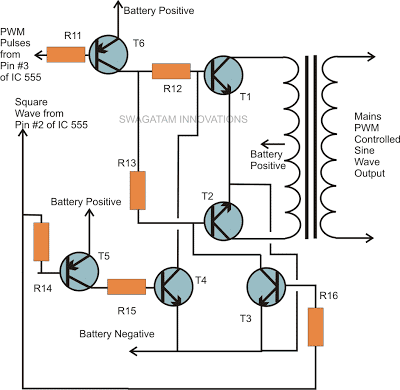
The above PWM output is applied to the output stage as shown in the figure.
Transistors T1 and T2 receive the PWM pulses at their bases and switch the battery voltage into the transformer winding according to the duty cycles of the PWM optimized waveform.
The other two transistors make sure that the conduction of T1 and T2 takes place in tandem, that is alternately so tat the output o from the transformer generates one complete AC cycle with the two halves of the PWM pulses.
Waveform Images:
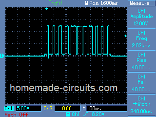
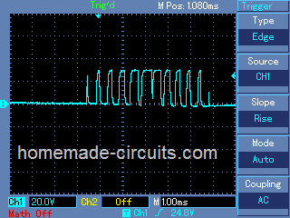
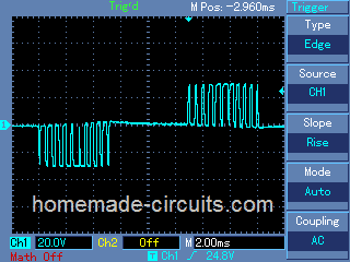
(Courtesy: Mr. Robin Peter)
Please also see this 500 VA modified sine wave design, developed by me.
Parts List for the above IC 555 pure sine wave inverter circuit
- R1, R2, R3, R8, R9, R10 = 10K,
- R7 = 8K2,
- R11, R14, R15, R16 = 1K,
- R12, R13 = 33 Ohms 5 Watt,
- R4 = 1M preset,
- R5 = 150 K preset,
- R6 = 1K5
- C1 = 0.1 uF,
- C2 = 100 pF,
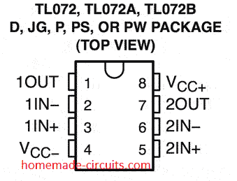
- IC1 = TL 072,
- IC2 = 555,
- T1, T2 = BDY29,
- T5, T6 = TIP 127,
- T3, T4 = TIP122
- Transformer = 12 – 0 – 12 V, 200 Watts,
- Battery = 12 volts, 100 AH.
- IC 555 Pinout

IC TL072 Pinout Details
SPWM waveform stands for sinewave pulse width modulation waveform and this is applied in the discussed SPWM inverter circuit using a few 555 ICs and a single opamp.
4) Another Sine wave Version using IC 555
In one of my earlier posts we elaborately learned how to build a SPWM generator circuit using an opamp and two triangle wave inputs, in this post we use the same concept to generate the SPWMs and also learn the method of applying it within a IC 555 based inverter circuit.
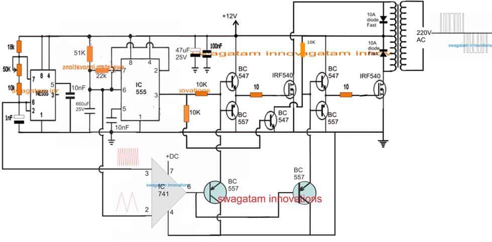
Using IC 555 for the Inverter
The diagram above shows the entire design of the proposed SPWM inverter circuit using IC 555, where the center IC 555 and the associated BJT/mosfet stages forms a basic square wave inverter circuit.
Our aim is to chop these 50Hz square waves into the required SPWM waveform using an opamp based circuit.
Therefore we accordingly configure a simple opamp comparator stage using the IC 741, as shown in the lower section of the diagram.
As already discussed in our past SPWM article, this opamp needs a couple of triangle wave sources across its two inputs in the form of a fast triangle wave on its pin#3 (non-inverting input) and a much slower triangle wave at its pin#2 (inverting input).
Using IC 741 for the SPWM
We achieve the above by using another IC 555 astable circuit which can be witnessed at the extreme left of the diagram, and use it for creating the required fast triangle waves, which is then applied to the pin#3 of the IC 741.
For the slow triangle waves we simple extract the same from the center IC 555 which is set at 50% duty cycle and its timing capacitor C is tweaked appropriately for getting a 50Hz frequency on its pin#3.
Deriving the slow triangle waves from the 50Hz/50% source ensures that the chopping of the SPWMs across the buffer BJTs is perfectly synchronized with the mosfet conduct ions, and this in turn ensures that the each of the square waves are perfectly "carved" as per the generated SPWM from the opamp output.
The above description clearly explains how to make a simple SPWM inverter circuit using IC 555 and IC 741, if you have any related queries please feel free to use the below given comment box for prompt replies.
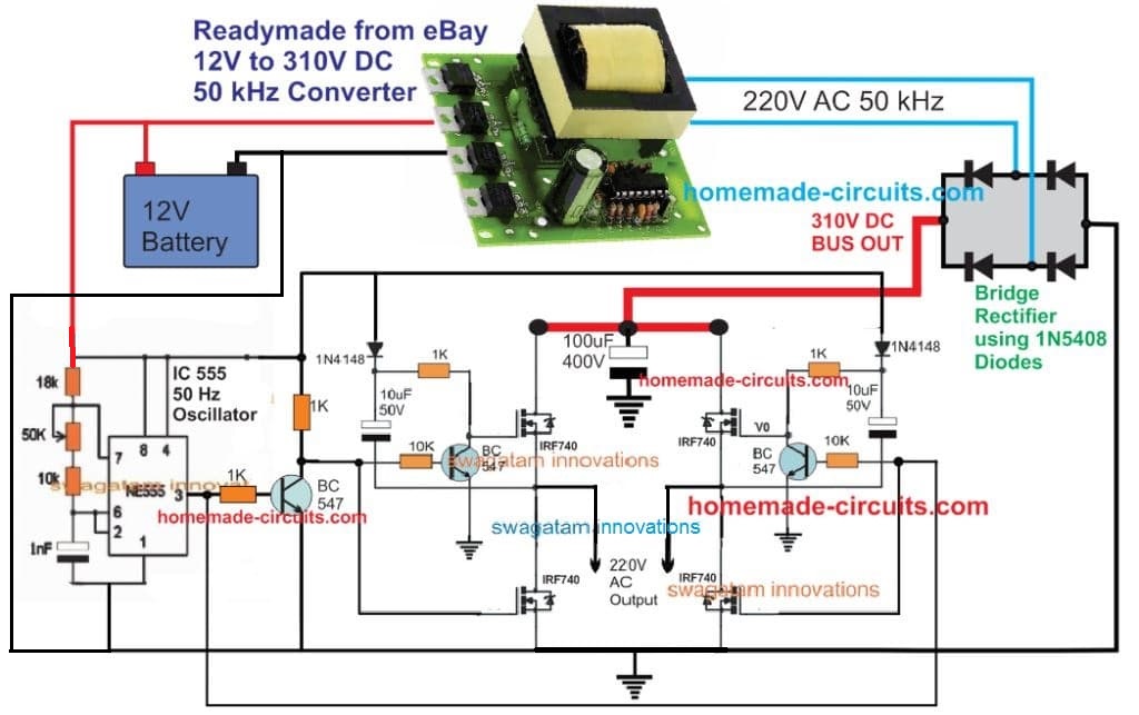
5) Transformerless IC 555 Inverter
The design showing below depicts a simple yet very effective 4 MOSFET n channel full bridge IC 555 inverter circuit.
The 12 V DC from the battery is first converted into 310 V DC through a ready made DC to AC converter module.
This 310 VDC is applied to the MOSFET full bridge driver for converting it into a 220 V AC output.
The 4 N channel MOSFETs are appropriately bootstrapped using individual dide, capacitor and BC547 network.
The switching of the full bridge section is executed by the IC 555 oscillator stage. The frequency is around 50 Hz set by the 50 k preset at pin#7 of the IC 555.
6) IC 555 Inverter with Automatic Arduino Battery Charger
In this 6th inverter design we use a 4017 decade counter and a ne555 timer Ic are used to generate a sinewave pwm signal for the inverter and an Arduino based automatic high/low battery cut-off with alarm.
By: Ainsworth Lynch
Introduction
In this circuit what actually happens is that the 4017 outputs a pwm signal from 2 of its 4 output pins which is then chopped up and if the proper output filtering is in place at the secondary side of the transformer it takes the shape or close enough to the shape of an actual sine wave form.
The first NE555 feeds a signal to pin 14 of the 4017 which is 4 times the required output frequency that you need since the 4017 switches across its 4 outputs, in other words if you need 60hz you would need to supply 4*60hz to pin 14 of the 4017 IC which is 240hz.
This circuit has an over voltage shutdown feature, under voltage shutdown feature and a low battery alarm feature all that is done by a microcontroller platform called the Arduino which needs to be programmed.
The program for the Arduino is straight forward and has been provided at the end of the article.
If you feel that you won’t be able to complete this project with the micro controller added it can be omitted and the circuit will work just the same.
How the Circuits Works
This IC 555 Inverter with Arduino Hi/Low Battery Shutdown Circuit can work from 12v, 24, and 48v going to 48v an appropriate version voltage regulator would have to be selected and the transformer sized accordingly also.
The Arduino can be powered with 7 to 12v or even 5v from a usb but for a circuit like this it would be good to power it from 12v as not to have any voltage drop on the digital output pins which is used to power a relay which turns on the Ic in the circuit and also a buzzer for low voltage alarm.
The Arduino will be used to read battery voltages and it only works from 5V DC so a voltage divider circuit is used I used a 100k and a 10k in my design and those values are plotted in the code that is programmed in the Arduino chip so you have to use the same values unless you made modification to the code or write a different code which can be done since the Arduino is an open source plat form and its cheap.
The Arduino board in this design is also connected up with an LCD display 16*2 to display battery voltage.
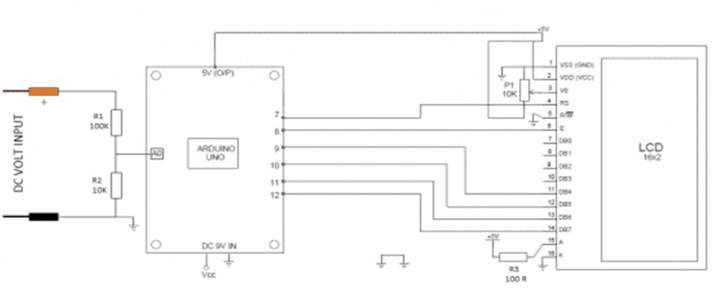
Below is the schematic for the circuit.

Program for the Battery Cut Off:
#include <LiquidCrystal.h>

LiquidCrystal lcd(7, 8, 9, 10, 11, 12);

int analogInput = 0;

float vout = 0.0;

float vin = 0.0;

float R1 = 100000.0; // resistance of R1 (100K) -see text!

float R2 = 10000.0; // resistance of R2 (10K) - see text!

int value = 0;

int battery = 8; // pin controlling relay

int buzzer =7;

void setup(){

pinMode(analogInput, INPUT);

pinMode(battery, OUTPUT);

pinMode(buzzer, OUTPUT);

lcd.begin(16, 2);

lcd.print("Battery Voltage");

}

void loop(){

// read the value at analog input

value = analogRead(analogInput);

vout = (value * 5.0) / 1024.0; // see text

vin = vout / (R2/(R1+R2));

if (vin<0.09){

vin=0.0;//statement to quash undesired reading !

}

if (vin<10.6) {

digitalWrite(battery, LOW);

}

else {

digitalWrite(battery, HIGH);

}

if (vin>14.4) {

digitalWrite(battery, LOW);

}

else {

digitalWrite(battery, HIGH);

}

if (vin<10.9)) {

digitalWrite(buzzer, HIGH)

else {

digitalWrite(buzzer, LOW

lcd.setCursor(0, 1);

lcd.print("INPUT V= ");

lcd.print(vin);

delay(500);

}
For more info you may feel free to express your queries through comments.


Comments
Sir am in need of 12v to 240v 200w sine wave inverter circuit sir
Samson, you can try the following design and customize it according to your specifications:
https://www.homemade-circuits.com/1500-watt-pwm-sinewave-inverter-circuit/
Thanks for your reply Sir.
I have made inverter using 555 timer and bc547 B transistor
Sir, I used 24-0-24 ,230V transformer I m getting 50 V output instead of 230 is it because I have not used 9-0-9 transformer?
Hi Dweep, yes that’s exactly why you are getting a reduced voltage output, please make it 9-0-9v, or at least 12-0-12v
Hi there! I love these circuits, they’re close to something I need. I have a range of 6V, 9V, 12V DC wall power adaptors… one of my devices needs a 9V AC adaptor, so I’m trying to find a simple 555 circuit that will produce about 9VAC, up to 300mA. All of the circuits I’ve found include a transformer to convert to 110-220V which is too much.
Do you have a circuit that could do low voltages AC?
(than kyou)
Hi, you can try the following design for converting 9V DC to 9 V AC
Thank you! I will give this a go.
Thank you too for replying very promptly. Have a great day
I am 73 and been in electronics for 50 years built my first 8080 based system in 1978. 2 deg’s aeronautics and computer science. Been in software most of life. done lots of repair work but have some UPS system that need repair, APC, Tripp-lite, and have not a clue what part of the basic block dia. to look for the most likely failure point. Have used logic probes on digital circuits before, does not help here. I know from previous experience that there is always a single part of failure that is higher probable then others, ie. power supply’s for most electronics. I am sure given more time I could find the problem but hoped you could give a hint where to look first. Feel I should have known this. Spent many years building ranch, training horses, and building barns, houses, etc. So time has been short for Hobbies (HaHa). Designed and build Ham Radio Equip. So some experience.
Thank you for sharing your experience in the field of electronics. I appreciate it. I truly wish I could help you, however without checking the entire circuit configuration of the UPS it may be quite difficult for me to suggest the exact fault.
Thanks sir, regarding your last comment, after connecting the diodes individually to each mosfet gate say for example we used 6 mosfets, 3 each separately are we going connect the whole diodes from each gate together through a common wire and take it singly to the Bc547 collector or are we going to connect the diodes together as they’re in threes and get two common wires to connect to the Transistor collector, sir pls if possible use a diagram to show us this
Then lastly sir, can we use this feedback circuit in any inverter using n channel mosfets or npn transistors because the article said that it’s applicable only to inverters with N channel or NPN transistors. Thanks.
Individual diodes will be necessary only if you are using separate resistors on each gate. So the anodes of the diodes will connect with respective mosfet gates, and the cathodes of all the diodes will join together and connect with the collector of the BC547 transistor of the inverter correction.
The feedback circuit can be used with all inverters having N channel mosfets.
Hello sir, good day I have gone through the write-ups you sent to me and I must confess that they are very helpful.
I have gotten the ones I need and joined them with the relevant inverter circuits and I want you to pls help me confirm that they will work so that I won’t make costly mistakes.
http://www.dropbox.com/s/gafkpcs5hpt27r3/inverter-output-voltage-corrector-circuit-1.png?dl=0
http://www.dropbox.com/s/f61n6zzcyh79mwy/screenshot_20211224-142052.png?dl=0
I sent you two circuits diagrams the first is an inverter circuit using irfz44 mosfets and TIP41C transistor. The second diagram is the diagram of the automatic feedback control circuit I integrated with the inverter circuit. Pls I want you to help check if joining both circuits together appropriately is okay and will work fine producing 50hertz and 220v A.C. I will give a detailed explanation on how I joined the two circuits for you to understand.
From the first diagram the points out for mosfets were connected to the gates of the two set of the IRFZ44 mosfets of the inverter ( diagram 2).
Then the sides out for 12v d.c. + and minus in diagram 1 were connected to the inverter’s ( diagram 2) 12v +& – terminals.
Then lastly the points out for the transformer from diagram 1 were connected to the output side ( 220v) of the inverter ( diagram 2) transformer. Pls check if these arrangements will work fine and if the inverter will sine wave a.c. Thanks.
Michael, I have explained the entire process and the connection details in the relevant article, if you are facing any problems you can ask me, I will tell you how to do it.
For multiple mosfets you will have to connect individual diodes from each mosfet gate to the BC547 collector.
Sir I have resent the message, pls check your spam folder. Thanks.
http://www.dropbox.com/s/oowqvbiddeskn4a/screenshot_20211224-142052.png?dl=0
http://www.dropbox.com/s/sjniqm8m3ie0cok/screenshot_20211223-161034.png?dl=0
http://www.dropbox.com/s/gox0rr8334ju7bg/screenshot_20211223-161200.png?dl=0
http://www.dropbox.com/s/xpq0sdacbfbahxu/screenshot_20211223-161121.png?dl=0
Sir I signed up on Dropbox, afterwards downloaded thier app and uploaded the images there, but you can view them using chrome. The third and fourth links are same circuits.
Like I wrote to you in my previous comments, all I want you to do is to help me to add the pure sine wave or modified sine wave and automatic feedback control circuits parts or diagrams to the circuit images I sent to you. Thanks and remain blessed as you do this. Compliments of the season ✨
Michael,
I already have all these information posted in this blog.
You can refer to the following post for learning how to convert an SG3525 inverter into pure sinewave……you can also get the feedback design in the 3rd circuit diagram from top:
https://www.homemade-circuits.com/sg3525-pure-sinewave-inverter-circuit/
For 4047 you can refer to the following post
Pure Sine Wave Inverter Circuit Using IC 4047
for general purpose feedback control, you can refer to the following article:
Automatic Inverter Output Voltage Correction Circuit
Ok sir, so sorry for the inconveniences, let me reduce it to three circuits only, pls sir how am I going to send the links to you and you will get them and they will be opening, because it’s giving me a lot of trouble here trying to find a way to send them to you and they will work. Thanks
You can upload it to any free image hosting site online, and provide the link here, if it is easy and feasible for me I will try to solve it for you.
Please remove the https while sending the links.
Ok sir, thanks, I have sent 6 different links for 6 inverter circuits just before this particular comment. you can view them using chrome or drive. The fifth and sixth circuits are same but they aren’t joined together, that’s why I made two different links for them
Sir pls all I want you to do is to help me to make these circuits pure sine wave inverters especially the first one and then add automatic feedback control to each of them if you can make the first one a pure sine wave inverter and others modified sine wave, I will be grateful for it, but if you can have time to make all the circuits pure sine wave, I’d be more grateful ????????????????, I know you’re a very busy person. Thanks again for doing it. Pls join the diagram of the pure sine wave/ modified sine wave and automatic feedback control circuits to each of them ( the inverter circuits below) so that I can understand it well
Concerning the second circuit link, pls it looks like this a modified sine wave inverter, am not sure, if it’s not pls help me to convert to pure sine wave/ modified sine wave like the others.
Thanks very much sir for getting out time to do this
Hello Michael,
first of all the links are not working because they are not shared.
Second thing is that I cannot join them because that would be a lot of work and time consuming for me.
Sir pls I have sent multiple replies, I don’t know if you have gotten any of it, if not pls send me your email lemme send the message directly through it. Thanks
Michael, I prefer discussing through comments, so you can send the details here, I will try to figure it out.
Sir I have sent you the for the circuit diagram as you requested using same email am using to send this message
Sorry Michael I did not get any email. Alternatively, you can upload it to any free image hosting site and provide the link here. Make sure to remove the https from the link.
Hellow Mr swagatam.,
how can I add LC pass filter to the 4th sine wave inverter before the transformer output in a half bridge inverter.?
Hi Micheal, according to me there’s no need to connect an inductor, because the transformer secondary itself acts like an inductor. You can simply add a 3uF/400V PPC capacitor across the output wires and that will transformer the SPWMs into pure sine wave.
Thank you very much Ing… .. I made the simplest square wave inverter and it works very well, from a probe and it works, then I will add it to be a sine wave…
http://1.bp.blogspot.com/-z9RRPSTi8zs/UbR4uKyuLRI /AAAAAAAAESo/rGu-sAhOqio/s1600/IC%204047%20inverter%20circuit.jpg I
ask: I don’t have an oscilloscope for now
. on pin 10 and 11 = 50 hz and on
pin 13 = 100 hz. del ic = 4047… .service ,, leave there .. ??
2- To adjust the frequency of 2 khz in pin 2 of ic2 555, I can adjust with a Digital multimeter .. ??
3- I wind my transformers, could I increase my 220vac turns to compensate for the voltage drop when adding the load, .. at what voltage could I increase in my calculation…?
Glad you could make the inverter successfully.
pin#13 can be left open.
you can adjust the frequency by keeping the meter probe pin10 and ground, or pin11 and ground
you can increase the secondary turns to increase the output voltage, but increasing voltage will reduce current which will again lead to voltage drop if the load is high.
Muchas gracias Ing….creo que me exprese mal,,,
Hice el inversor de onda cuadrada más simple y funciona perfecto, luego lo agregaré para ser onda sinusoidal….pero necesito saber para proseguir ,,se que para ver la forma de onda es imprescindible
1- Puedo ajustar con un Multímetro Digital la frecuencia en el pin 10 y 11 con respecto a tierra.del 4047..?? de hecho así ajuste el 1er inversor que mencione..o debería hacer con Osciloscopio..?
2- Como queda para ajustar la frecuencia de 2 khz en el pin 2 del ic2 555, puedo ajustar con un multímetro digital..?? o para esta zona debería hacer con Osciloscopio..?
Yes, You will need an oscilloscope to confirm the waveform.
1) To adjust the frequency you can use a multimeter (set at frequency range), across pin10 or pin11 and ground. Oscilloscope is not required.
2) For iC 555 also you can use a multimeter (set at frequency range) to adjust the frequency at pin#2. Oscilloscope won’t be required here too.
Mil….Gracias..Ing….. pregunto..para avanzar ,,cada ítem por favor !
1- Puedo ver la forma de onda con el programa Goldwave..en mi pc.
2-Cómo le inyectó la señal al MIC (Micrófono)., a través de qué.? transformador con baja espira 1Vac, sería señal alterna. o le aplico señal del integrado al la entrada de MIC (Microfono)..
3- Antes de usar el Goldwave para ver la señal del inversor,, podría probar para ver la señal de un transformador 220Vac -en el secundario le agrego 1 a 3 espiras q me de 1 Vac o menos..
Ing,mil gracias y disculpe la falta de comprensión,,Pregunto,,para ver la ,forma de onda con el programa Goldwave.,
Cómo le inyectó la señal a la entrada del Micrófono de mi pc,,.?
1- segun entendi, antes de meter señal a la entrada del Micrófono de mi pc debo usar con una resistencia de alto valor, así verificare la señal de cualquier secundario de transformadores de 220 V y de paso ya veré la salida de mi transformador inversor,,,,
2- Para ver la forma de onda de los 555 uso resistencia,,?,o es directo sin resistencia..? que valor será ..?
As far as I remember, the input voltage to the PC MIC socket for operating Goldwave should be 1 V peak to peak.
So you may have to use a potential divider and step down the AC voltage to 1V and then feed it to the MIC socket, for sending the signal to Goldwave.
You are welcome!
1) yes, Goldwave can be used for seeing the waveform.
2) Sorry I did not understand the use of MIC with an inverter?
3)Yes 220V transformer secondary can be checkd in any pc software through a high value resistor.
EXELENTE SITIO….podrías decirme Ing..cual de los 6 circuitos u otro , me recomendaría usar para encender tubos fluorescentes tengo desde 5w a 40w necesito circuitos para 12Vdc y 220Vac
Thank you and glad you liked the concepts. You will have to use a sine wave inverter for operating a fluorescent tubelight, so that it works without noise. You can make the 555 sine wave version of the inverter, or you can also go with the second 4017 schematic from the following article, which is much easier modified sine wave inverter and will give fairly good results:
https://www.homemade-circuits.com/modified-sine-wave-inverter-circuit-2/
Sir swagatam,about first basic design circuit, what size of mosfet can be use to get a 5000w ac output?
Luis, MOSFET is a secondary thing, first you will have to dimension the transformer ad the battery appropriately, then the MOSFET can be selected accordingly:
Calculate Battery, Transformer, MOSFET in Inverter
ok thanks for the answer sir
Dear Sir,
In your no 4 sign wave inverter circuit (Another sign wave version using ic 555) where you used two 555 timer ic one 741 opamp and two irf540 power mosfet, what will be its max watt if I use 12-0-12 5 amp transformer ? Can I use four 540 mosfet and same transformer for more watt and what will be its interchange of components ? If possible then plz send me the same circuit diagram.
Thanking you.
Hello Sekhar, MOSFETs are like switches, they only switch power they don’t increase power, the wattage or power is determined by the transformer and the battery…the MOSfET must be rate according to their max power. A 12V 5 amp will produce only 50 watt of power at the output
Dear Mr. Swagatam,
Do you recommend connecting transformers in parallel for use in an inverter application, since i have on hand two 500VA transformer units procured from old UPSes, both same in size, weight, input/output voltage and power.
The transformers have PRI 2 in pins and SEC 2 out pins.
My questions are:
1. Can i connect them in parallel with the idea of having a 1000VA power from it.
2. I have noticed that on paralleling the windings, the resistances of both stages drops down to much less than half of what each transformer had.
(To clarify: pri to pri and sec to sec together).
Still, for safety I never applied mains energy to the transformer setup i made.
3. Do paralleling two transformers for more output power dangerous for the inverter circuit either being made by hand or getting ready-made procured inverter cards.
4. Is this something sensible we can do or try? what about the heat distribution between them, if we setup the sufficient spacing and ventilation between them?
I do prefer making circuits from your site since i trust them from a great long time.
Dear Sherwin,
If the specifications of the transformers are reasonably equal then you can connect the primary sides in parallel in an inverter application.
But I won’t recommend connecting the secondary or 220V side in parallel, due to the risk of opposite polarity connection, and a slight mismatch in the specs might result in wastage of power.
So the primary DC side can be connected in parallel to the inverter, and the secondary side could be individually connected to separate loads.
Thank you for trusting my circuits, It’s my pleasure!
You will have to provide me the link here so that I can check it out. After posting the link write another comment informing me about it so that I can retrieve it from the spam folder.
Thank you sir for your reply sir but pls can I upload them directly from my email app for you to see pls.
Michael, sorry there’s no image upload facility in this comment section, so at the moment it is not possible to discuss external diagrams. You can try google drive sharing, however sending any sort of link through comments here will cause the comment to go into the spam folder.
Good day sir, pls I want to share some circuit diagrams with you for you to help me to answer some questions on them, pls how am to share it or send them to you. Thanks.
Did you verify the current and voltage with meter?