For anyone who is searching for an audio amplifier with massive output power in the order of 100 watt to 200 watts, using an absolute minimum parts count, this particular circuit will accomplish it.
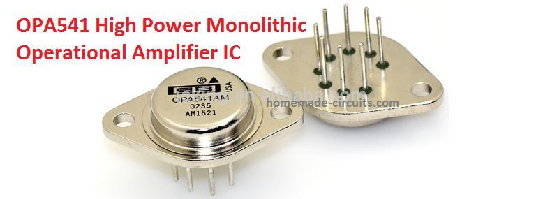
How the Circuit Works
The IC OPA541 from Burr-Brown is a power opamp is specially designed to work from power supplies up to ±40 V and for providing continuous output currents up to as high to 5 A and 10 A peak.
This simply means that if the IC is sufficiently cooled using heatsink and fan cooling, the probable amplification output could be well over the 160 watt mark.
Built-in current limiting feature of the device could be programmed (preset) by the user through a solitary external resistor, which can safeguard the amplifier and the load from erroneous output situations.
Although the OPA541 is typically designed for driving motor, servo amplifiers and programmable power supplies etc, according the Burr-Brown sources, it can also work amazingly well when used as a high power audio amplifier.
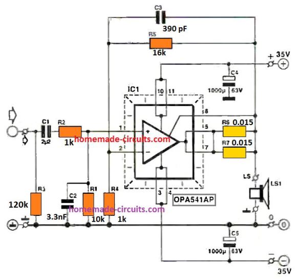
The schematic discussed in this article will deliver approximately 60 watts to 160 watts into an 4 Ohm load. This is accomplished through a a symmetrical supply voltage of ±40 V.
The in-built current limiter of the chip is fixed to an switch ON threshold of around 8.5 A through parallel linked resistors R6/R7.
Programming the Output Current
This current limit makes sure that the optimum drive margin can be achieved even when a 4 Ohm loudspeaker is used.
But remember, although, that R6 and R7 limit the current below the overload threshold it doesn't make the amplifier short-circuit proof, because that might call for a current threshold of 1.8 A, if we consider the 1C operation inside its SOA (safe operating area).
The value of the resistor, Rcl, (R6+R7) which provides the current limiter switch ON or activation point, could be determined using the formula:
Rcl = (0.813/Iabs) - 0.02 [Ω]
In actual operation the positive half cycle of the output current gets restricted quite earlier, at around 10% at a lower level than the pre-programmed threshold.
The contrary might occur for the negative current, that may be approximately 10% more than the predetermined value.
Total Harmonic Distortion
The amplifier distortion output is appreciably low. The THD value continues to be nicely under 0.5% within the entire sound spectrum, with a condition where a gain of x6 is fixed (R5 will then be approx. 5 kΩ) and a supply voltage of ±35 V.
Because the IC functions at a quiescent current of hardly 20 mA, cross-over distortion might initiate rather quickly.
To keep the THD to a minimum level the assumptive bandwidth is, restricted to approximately 22 kHz through capacitor C3.
Input filter network made using R2-C2 helps to minimize IMD (inter-modulation distortion), and lowers the true bandwidth to approximately 16.6 kHz.
The low frequency roll-off is fixed to 6.6 Hz by R1-C1. The IC should be installed over a relatively large heatsink having a thermal resistance of 1.2 KW or higher.
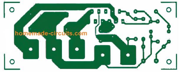
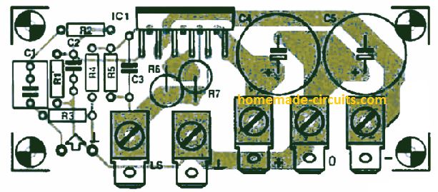
PCB Design


Questions & Answers
I want to run this circuit using 28-0-28 d.c. (+&-). Will it work? I am aiming for approximately 30W/8E, 60W/4E. I already have a hefty transformer that will give me these voltages after rectification. I want to use my own Audio valve pre-amp which works and sounds excellent.
Yes, 28-0-28 d.c. is quite a health supply for this amplifier design, and you can definitely use it to get the specified amounts of power outputs…
gracias ing, xser de mucha utilidad todos sus proyectos el OPA 541 ES MUY BUENO y facil de construir, nuevamente gracias.
Thank you Luis, for your kind feedback, I appreciate it very much…
Sir, good morning, I live in Dhaka Bangladesh, I need this IC opa541 – qty 02
Hello Rashidul, I do not sell electronic spare parts, so can’t help you in this regard
The 160 watt amplifier we are using is used to switch off when speaking loudly, I mean the reset butting push off.what will I do to correct it or stop it.
Sorry, I can’t figure out how this can be implemented in the above circuit??
Hi
what is the job of the condensator (C4) that is connectet to +35v ?
Hi, it is for added filtration, so that there is minimal hum at the output
Very useful circuit. Hobbyist can easily follow. Thank you.
Dear sir,
Please sir, help me with the test circuit to check the workability of this IC 4558D
Hello Godfrey, I cannot find any IC 4558D in the above article, which circuit are you referring to?
Please sir, am not referring to any circuit you have posted.
But I just want to know how to test the IC, as in if there is a test jig circuit for the IC or any way to check the functionality of the IC
The above article is about a power amplifier, not an op amp, please ask your question under an op amp related article.
Hi,
I am a DIY enthusiast.Would like to have construction details of 3 way sealed enclosure like the vintage Indian Philips with woofers ,Tweeters and squawkers. Though we may not get the Philips drivers and crossovers now,can you ps suggest some present drivers and crossovers along with box dimensions.I would prefer 10 to 12 inch woofers.and Wattage say up to 100W RMS.
Grateful
Chaks
Hi, If possible I’ll try to find the required circuit for you and update in this website
In the meantime you can try the following design which is quite similar to the required specs.
https://www.homemade-circuits.com/making-center-speaker-box-c80-for-surround-sound-systems/
Thanks ,I did have a look .
Grateful
Chaks
Glad to help!