In this post I have explained how to design audio filter circuits such as high pass filter and low pass filter circuits effortlessly without going through the hassles of complex simulation and calculations. The presented designs will enable creating filter circuits only for the desired specific frequency bands and block all other unwanted frequencies.
What's High Pass Filter
As the name suggests a high-pass filter circuit is designed to attenuate all frequencies below a particular selected frequency, and pass or allow all frequencies above this threshold. The principle is just opposite to a low-pass filter circuit.
The cut-off range is generally at a relatively higher frequency range (in kHz),
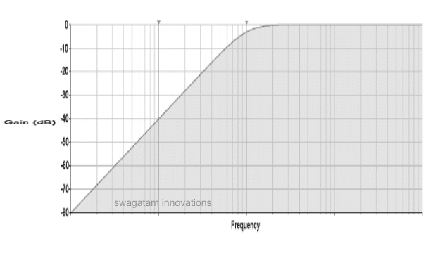
The following high pass filter response graph shows the waveform image indicating how all frequencies below a selected cut-off threshold are attenuated or blocked gradually, as frequency decreases.
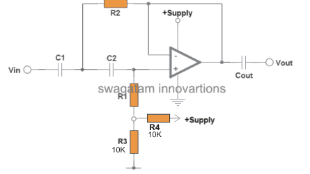
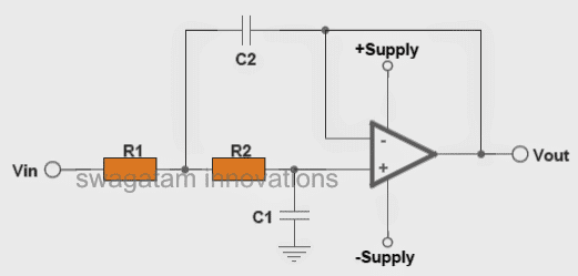
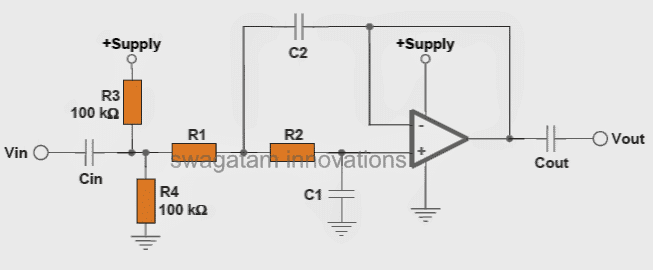
The following two images are configured as standard high-pass filter circuits, where the first one is designed to work with a dual supply whereas the second one is specified to operate with a single supply.
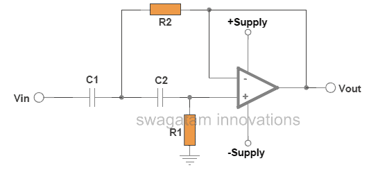
In both the above configurations, the opamp forms the central processing active component, while the associated resistors and capacitors wired across the input pins of the opamp are introduced for determining the high-pass filter cut-off point, depending upon how the values of these passive components are calculated as per the users specifications or requirements.
How to Design a Customized High Pass Filter
As proposed, to design a high-pass filter circuit quickly, the following formulas and the subsequent steps can be used for calculating the relevant resistors and capacitors.
First, select an appropriate value arbitrarily for C1 or C2, both can be identical.
Next, calculate R1 by using the following formula:
R1 = 1 / √2 x π x C1 x Frequency
Here the term "frequency" refers to the desired high-pass cut-off threshold below which other unwanted frequencies need to be attenuated or ignored gradually.
Finally, calculate R2 in the same way as above using the following equation:
R2 = 1 / 2 √2 x π x C1 x Frequency
The single supply version of the high pass filter circuit can be seen involving another capacitor Cout which is not at all critical and can be approximately 100 or 1000 times more than C1.
The above discussions shows how simply anybody can calculate and design a high-pass filter circuit quickly for a particular application which could be a treble control circuit, a 10 band graphic equalizer or a home theater circuit etc.
How Low Pass Filters Work
As the name suggest low pass filter circuits are designed to pass or conduct a preferred range of frequency lower or below a desired cut-off threshold, and attenuate or gradually block the frequencies above this value.
Normally opamps are employed for making such filter circuits, since opamps are best suited for these applications due to their extremely versatile characteristics.
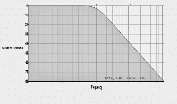
Graph Showing Frequency vs Gain
The following graph provides the typical low pass filter frequency response with regards to the gain, we can clearly see how the response attenuates (gradually drops) as the frequency increases past the particular cut-off threshold.
The following images depict the standard opamp based low pass filter circuits. The first one needs to be powered by a dual supply, and the second one works using a single supply voltage.
Designing a Customized Low Pass Filter Circuit
The components R1, R2, and C1, C2 configured with the non-inverting (+) and the inverting (-) input pinouts of the opamp basically decide the cut-off range of the filter, and these need to be calculated optimally while designing the circuit.
For calculating these parameters and designing a low pass filter circuit quickly within minutes one can utilize the following formulas and the explained steps:
First we need to find C1 which we can do by selecting any value arbitrarily as per our convenience.
Next, we can calculate C2 with the formula:
C2 = C1 x 2
R1 and R2 can be identical, and can be calculated using the following formula:
R1 or R2 = 1 / 2 √2 x π x C1 x Frequency.
here the "frequency" is the range where the cut-off transition is expected to happen, or the desired cut-off range.
The values of Cin and the Cout shown in the single supply low pass filter are not critical and these can be anything 100 to 1000 times that of C1, meaning if you selected C1 as 0.1uF, then these could be anywhere between 10uF and 100uF etc. The voltage spec may be selected to be twice that of the supply voltage used.
The resistors are all 1/4 watt rated, 5% or 1%.
That's it!.... using the above simple technique you can design a reasonably good low pass filter quickly and use it for a specific application which could include a high bass music circuit, an active speaker cross over network or a home theater system etc.
High Pass, Low Pass and band Pass from a Single Circuit
A state variable filter such as the one shown below can generate three outputs: high pass, band-pass, and low pass. This is therefore an extremely flexible filter design, specially if the resonant frequency is featured to be adjustable.
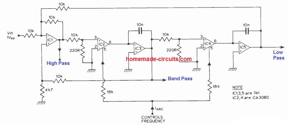
In the proposed filter design, this specific resonant frequency is linearly proportional to the gain of the two integrators. A couple of CA3080's, (IC2, 4) are actually configured to supply the adjustable gain, the resonant frequency being held proportional to the current IABC.
Working with 741 op amps for IC3 it may be possible to get a control range of 100 to 1, (resonant frequency). If the ICs CA3140's are applied in place of 741's then this range could be expanded to practically 10,000 to 1.
More Info: https://drive.google.com/file/d/1yo_WH0NzYg43ro_X0ZrXoLYSM5XOzKU8/view?usp=sharing


Questions & Answers
Dear
i have one voice playback ic aPlus ap89341k. While i record this ,mfg give me 2 separate output pin for audio & 1 pin give me push pull signal while other 2nd pin give me DAC audio signal. Now i connect this out to TDA8022 amplifier ic . Then what signal give me clear sound push pull or DAC? i need clear sound without noise. May i used some opamp base hi pass/low pass ckt with DAC out & then give opamp out to amplifier?
Nitesh, Please use the DAC output and connect it with the TDA power amp through an opamp based low pass filter.
Thanks
Can u pl suggest me OP amp base low pass filter. May i use MC6002 OR TL074?
You can try any of the circuits explained in the following article:
https://www.homemade-circuits.com/simple-tone-control-circuits/
ok
Combining high and low pass filter with an adder circuit crates a 180 phase. How do I shift the phase?
Hi ,i couldnt find ca3080 which ic i should replace with it in that full circuit? I mean in full high pass,band pass and law pass one.can i replace lm741?plz answer me soon????????
Hi, for CA3080 you can try the following replacement:
https://www.nteinc.com/specs/900to999/pdf/nte996.pdf
Thank you so much ,i also have another important question ,in that complite circuit resistor is 4.7 k or 47 k? Or its 4?
You are welcome! The 4K7 resistor is equal to 4.7 K
hi swagattan!apart from JRC4558,Which equivalent opamp ic is more powerful than it?(am haron from Kenya)
Hi Haron, I am not very sure about it, but the datasheet says that each op amp inside 4558 op amp is equivalent to uA741 IC.
Hello All, I have ten LED VU two channel meters put together as a 20 channel display. I wish to design a circuit that will emulate on the display a Audio Spectrum Analyzer from 30 Hz. to 16Khz. All in all I believe that I need to construct 20 high/ low pass filter circuits. I have tried using a sort of bass -treble circuits with poor results. Any help is welcome.Thank you for your time.
Robert KB3LNN
The bass treble circuits must have a wide range. I guess tone controls using op amps should provide a good range and performance. You can try adding one of these circuits and check the results:
Simple Tone Control Circuits
Make this Bass Booster Speaker Box
5 Watt Stereo Amplifier Circuit with Bass Treble Controls
Hi Swagatam,
Your high pass, band pass and low pass filters in a single circuit has ca3080 special op-amps for two of the components. These are obsolete and very expensive if found. What op-amp substitute would you suggest?
Thanks!
Hi Norman, you can replace it with any modern high performance op amp
Hallo sir,do yu have any complete active high pass filter, cct diagram, tl 072 .single supply, (5khz). Lot of cct available with dual supply, but not a single one, with single supply, please design the cct, Thanks
Hello Rajesh, the high pass circuit using single supply is also given in the above article.
Thanks for ur reply, I’m looking for complete cct diagram, cut of frequency 5khz, with single supply, HPF, I hope yu understand, complete cct diagram THANKS
Hai sir..
My doubt regarding subwoofer power Amplifier section.
For jbl 1500w 12inch subwoofer which POWER AMPLIFIER IC will be good sir..
STK 4191
Or
TDA7294
Or
TRANSISTOR 5200 1943
Or
MOSFET..
If any other IC also kindly tell me sir..
And i also need the transformer rating of that IC.. Please guide me sir..
Hi Kesav, both the ICs are suitable for a low power around 300 watt subwoofer, they won’t be able to drive a 1500 watt subwoofer speaker…
Sir jbl 12inch subwoofer RMS 325W Max Power 1500W.. I need smooth bass sir.. Which IC will be best and kindly tell the transformer ratings of that IC
those ICs are for amplifying only…they will not give bass effect
Kesav, you can try the bass circuit from the following article:
https://www.homemade-circuits.com/extended-high-bass-effect-from-small-speaker-box-cross-over-filter/
or the last circuit from the following article:
https://www.homemade-circuits.com/10-band-graphic-equalizer-circuit-for/
Thank you sir
Can I use electrolytic capacitor instead because 10uf-100uf is scarce here.
yes you can!
I need to build a low pass audio circuit using a single supply. Cutoff frequency (Fc) is 500 Hz.
My question on the formula used to calculate R1.
Is this correct? R1 = R2 = 1 / [ 2 x Sqrt (2 x Pi x Fc x C1 ) ]
I want to use a 741 Op amp
The formulas are given in the article, please check them, IC 741 can be used
Thank you swag
Yes I read the formula in the article but wanted to verify it by submitting (for your review) the same formula with additional brackets around the denominator term. My viewer may not have displayed the original formula as written.
Regards Bob Little
Hi Robert, OK I understood what you mean to say, your equation needs a correction, The root symbol must be only for 2, and not for the rest of the expressions.
its good circuit ….
i need ur help…
how to design an amplifier circuit ? i mean suppose i want to design 200watt ampli. so what should i do…sstep by step.
will u suggest me a good book for designing a circuit.
Thank you.
thank you, amplifier is a huge subject and cannot be accommodated inside a single article, still I'll consider the suggestion and possibly try to include the same in my website soon
by the way there are many online tutorials which you can refer to in the meantime…
Thank you!