This simple MOSFET tester does a quick job of testing both enhanced mode type N and P-channel mosfets. It checks for shorts between gate, drain and source.
Designed By: Henry Bowman
It also distinguishes between N and P-channel mosfets. Once the connections are correctly made to the mosfet, all testing is done without reversing connections. This saves handling the pins and static buildup, which can produce erroneous results. This project uses a similar principle that I used to design a transistor test/identifier.
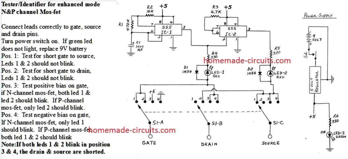
Circuit Operation:
IC-1 is a 555 timer IC configured as an astable multivibrator. It produces about two output pules per second.
The frequency is determined by R1, R2 and C1. The output of IC-1 is connected to resistor R4 and the trigger input lead of IC-2. IC-2 is also a 555 timer IC and configured as an inverter.
The output pin 3, of IC-2, is always the opposite polarity of the output pin 3 of IC-1. IC-2's output is connected to resistor R5. R4 and R5 provide current limiting to diodes D1/D2 and Led 1/2. The diodes and leds are connected to a 4 position, 3-gang rotary switch.
The three common leads of the rotary switch are connected to test posts labeled "gate", "drain", and "source" for mosfet connections. PG type clips with cords should be attached to the three binding posts for easy connections to the mosfets.
How to Test
When a mosfet is correctly connected to these connections and the power switch is turned on, the tests are as follows:
Position #1: Tests for a short between the gate and source connection. The outputs of IC-1 and IC-2 are continually reversing polarity.
If a short exists between gate and source, a current path is provided for Led-1 and Led-2 as both 555 ic's alternate polarity. If no short exists, no Led's will light.
Position #2: Tests for a short between the gate and drain connections. Moving the selector switch to position #2 also moves the Led connections to gate and drain. If no short exists, no Led's will light.
Position #3: Provides a positive bias to the gate, while drain and source are connected to the Led's. If the mosfet is N-channel, both Led-1 and Led-2 will blink. If the mosfet is P-channel, only Led-2 will blink. This indicates the normal diode function between gate and source. (See note below)
Position #4: Provides a negative bias to the gate, while drain and source are connected to the Led's. If the mos-fet is N-channel, only Led-1 will blink.
This indicates the normal diode function between gate and source. If the mos-fet is P-channel, both Led-1 and Led-2 will blink. (See note below)
Note: If the mosfet's drain and source are shorted, then both Led-1 and Led-2 will flash in test position #3 and test position #4, regardless of N or P channel. This is how a drain-source short is determined.
Parts List:
Qty - Description
2 ---- 555 Timer IC's or 1 Dual Timer 556
1 ---- 470K 1/4 watt resistor
1 ---- 10K 1/4 watt resistor
1 ---- 4.7K 1/4 watt resistor
1 ---- 1000 NF electrolitic capacitor 20 WVDC
3 ---- 330 ohm resistors 1/2 watt
2 ---- 1N34 general purpose diode, or equivalent
2 ---- Light emitting diode, red
1 ---- Light emitting diode, green
3 ---- Led mounting sockets
1 ---- Selector switch, 4 position, 3-gang
1 ---- Selector switch knob
1 ---- Toggle switch, spst
1 ---- 5 volt regulator 7805, or equivalent
1 ---- 9 volt battery
1 ---- 9 volt battery holding clip
1 ---- 9 volt battery post connector
3 ----binding posts for test connections
1 ----small apparatus box

Questions & Answers
Dear Sir,
Suppose I am running a DC motor via single transistor using PWM.
In case if mosfet is shorted means all of its three pins are shorted.
Will DC motor run at its full speed or will it stop and no current will flow through it?
.
I am asking it because I want to Run DC motor rated @ 110v using PWM. Actually 220v will be converted to 110v and below using adjusting duty cycle.(Please warn me if this is not good idea)
.
I am worried if at some stage my mosfets get shorted or burn down. Will my motor get 220v or all of the current will cease to flow trough the mosfet.
Waqar, nobody can predict whether a faulty device can result in short circuiting the output or in an open circuit…we cannot predict that.
By the way in PWM the peaks will be always equal to the input peaks, so in your case the motor would be getting 220V peaks always but through PWM this would be applied in pulsed form allowing the average voltage to drop down to some lower values, depending upon the duty cycle rate.
For safety you can add a fuse in series with the motor.
I will add a fuse.
Thanks Bro.
Hi Swagatum
Hope you,re well
I simulated this cicuit because i was doubting the operation,position 3,N-channel mosfet:both led 1 and 2 blink.But when i put a p-channel fet no leds blink?.
What am i not understanding?
Regards Robin
Welcome back Robin, Glad you tried to simulate this circuit, however this was designed by Mr. Henry who is one of the avid readers of this blog, and this has been tested by him successfully. So I am not sure why the simulation results are not complying.
May be a practical test would confirm the truth.
Keep up the good work!
Thanks for getting back to me Swag
I was busy with an inverter which was giving me a few problems and wanted to make sure the mosfets were’nt the problem thats why i had a look at this circuit which confused me even more but will take your advice
Thanks
You are welcome Robin, you can also use the following simple method to ensure your mosets were fine
https://www.homemade-circuits.com/how-to-check-mosfet-using-digital/
I was wondering if you could do me a favor I know this is dumb but could you email me a picture of the selector switch and binding posts that you would recommend and possibly a picture of how you would simulate this onto a bread board. Please sir
Sorry Colby that looks difficult at this moment due to lack of time
Good day Sir, please for MOSFET with 200 vgs what is the maximum inverter input can it take.
Seun, do you mean VDS? maximum power will depend on VDS, ID and ambient temperature!
Yes vds-200v, Id=49amps
What will be the maximum voltage input
12v VGs, and 200V VDS
You will have to check at what current and voltage the MOSFETs stays reasonably cool or warm with a big heatsink installed. That will be the power the inverter can transfer. For example if the MOSFET begins heating up uncontrollably at 48 V 30 amps, then it may not be suitable for 48 x 30 = 1440 watts, you must try a lower current and so on….
Allo monsieur,de vtre position,est ce que on peut trouver un pdf diagramm
de l’onduleur Heart interface freedom 20.SVP
Hello!
Multipole switch is expensive, but you can omit it by using a dil socket. Actually you do not need any fixing: use (dil8 a) pin 1, pin8, (dil8 b) pin1 and 8 for gate (or source) and leave pin 4 & 5 void.
For loose fet system is faster than a switch. With jumper wire & alligator clips you can connect more or less in situ components.
There is an error in the last note (in usage examples), I believe: should be led 1&2 in the case 1&2?
Yours
pg
Thank you for your valuable feedback, appreciate it very much…