In this post I have explained a simple sound to flashing lamp circuit which can be used for facilitating people with hearing loss, so that they are able to visualize a distant cell phone rings through flashing of a lamp, and immediately understand regarding an incoming call in their cell phone.
The following explanation and the circuit design was contributed by Mr. Henry Bowman to this site.
How the Circuit may Help a person with Hearing Loss
The presented cell phone ring tone to lamp flasher indicator circuit is specially designed by me for my wife’s sister, who has a cell phone and cannot hear the high pitched ring signal.
I’m using a small ceramic mike coupled to a TL082 preamp and it will be coupled to a 555 IC. She will lay the cell phone on top of this box.
When the phone rings, the TL082 will trigger the 555. The 555 will start a slow off and on pulse to a 12 volt relay.
The relay will operate a 60 watt light bulb off and on, so she can visually see the signal. I’ve got the power supply and voltage regulator built and working on the ic’s now.
Well, after finally finishing this project, I took it to my wife’s sister home yesterday. It worked great and my wife was able to call her from our home last night. We were having to make trips to her home to check on her and now she can see the flashing table lamp.
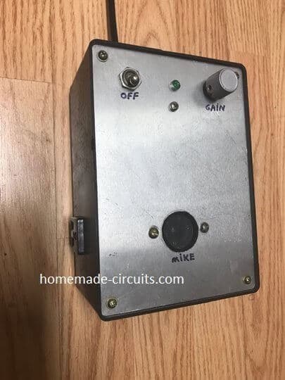
The TL082 did not have enough gain, so I changed to a transistor amp. I also found out that by changing the cell phone ring to interrupted, instead of continuous, I could eliminate the 555 timer pulse to the relay. The photo shows the side outlet on the box that the table lamp plugs in.
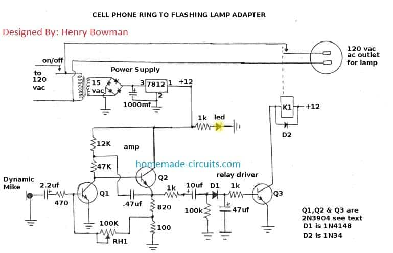
The box is 5” X 7” and houses the step-down transformer, voltage regulator, amplifier and 12 volt relay. Tried to improve on the schematic so it won’t appear scribbled like the first one. I don’t know what to do about the disclaimer for the coil and led.
Circuit Operation:
This cell phone ring to flashing lamp circuit is designed for people who have difficulty hearing the cell phone ring signal. The cell phone ring should be set to an interrupted tone signal.
A table lamp with 60 watt maximum bulb should be placed in the auxiliary side outlet. The cell phone's speaker should be placed on top of the dynamic mike.
When the cell phone rings, the table lamp will flash, on and off, indicating an incoming call. A gain adjustment is provided to reduce interference from loud noises, or conversations.
The original design of the dynamic mike amplifier specified Q1 to be BC549C transistor and Q2 to be BC547. Both of these transistors are high gain type with a maximum current gain of 800.
I didn't want to order a minimum of 50 each, so I modified the circuit to use the common 2N3904. These transistors have a maximum gain of 150.
I replaced a resistor with RH1 potentiometer for gain. I replaced a 2.2uf capacitor to the left of D1 with a 10uf value. I added D1, 1k resistor, Q3 and 47uf capacitor, K1 relay and D2.
D1 rectifies the ac signal to operate Q3.
D2 provides for clamping the inductive voltage from K1 and protects Q3. If you decide to use the original specified transistors for Q1 & Q2, you can eliminate the 47uf capacitor to the right of D1.
The 12 volt relay contacts should have a minimum contact rating of 1 amp at 120 vac. The lamp bulb should be 60 watt maximum, or smaller.
Note: The ac signal to dc, which allows Q3 to provide current to operate K1 relay. D2 provides for clamping the inductive voltage from K1 and protects Q3. If you decide to use the original specified transistors for Q1 & Q2, you can eliminate the 47uf capacitor to the right of D1. The 12 volt relay contacts should have a minimum contact rating of 1 amp at 120 vac. The lamp bulb should be 60 watt maximum, or smaller.
The Completed Prototype Image:


Questions & Answers
Hi, Just joined. Found this spot, not a comment but a question. I have an anemometer that puts out a DC pulse for each rotation of the cups. The pulse amplitude is proportional to the DC input to the system, can be anywhere between 0 to 12 v. Of course only the repetition rate of the pulse is used at the output. Your schematic of a stepping motor using a 555 timer clocking a 317 input, I would like to clock the 317 with the output pulse of the anemometer. Please show me how to do that. Thank you so much.
You have a great website and I appreciate any suggestions on my project. I am an 88 year old retired electronic technician. I date back to the vacuum tube days.
Perfect! Thank you so much for your help. Regards, Jack Shubert
Glad you liked it!
Hi, I’m sorry, bad typo. I should have said: CD 4017 or similar decade counter IC typically used in a stepper driver motor. As I view the pulse output of the anemometer, I can’t really say what the pulse width might be as I can’t get my scope sync locked in. I have to view the output of the anemometer as a ‘black box’ as I hesitate taking it apart. It may use a Hall circuit or even a reed switch, just guessing. I mention using a stepper driver as I have a few boards in my collection. Obviously I don’t plan on the anemometer driving a motor but I can take it from there. Any idea’s for a simpler circuit would be appreciated. I thank you very much for your prompt replay, not many folks today would do that. Jack.
No Problem jack, I have tried to design it for you, you can find it in the following link:
Please bear the 4017 pin details which are inverted in the figure due to some reason. If you are unable to identify them, please let me know.
The 1uF can be reduced to some lower value in case the anemometer speed is too high, and the circuit fails to respond correctly.
Hi, Are you referring to an LM317 voltage regulator circuit for integrating with the anemometer? Please clarify this, I’ll to figure it out.
Hi Swagatam and Henry,
I’m totally deaf and this phone-modd looks like it could be useful for me. I imagine the circuit could be used equally well for our local 230v AC.
Good stuff and thank you!
John
Thanks John,
we are glad you liked the concept and found it useful.
wish you all the best, please do keep posting.
for 220V operation, you just have to change the transformer with 220V to 12V winding specs.