The simple bathroom lamp timer circuit features a delay OFF timer which switches OFF the triggered lamp after a set predetermined time delay, additionally the circuit also includes a delay ON timer circuit which is appropriately set such that a warning tone is generated a few seconds before the lamp is about to shut off. The idea was requested by Mr. Enrico.
Circuit Objectives and Requirements
- I want to make a bathroom light timer switch with IC555, but i want to add a warning alarm sound before the lights goes off when the time limit is reached, can you help me?
- Buzzer is DC type and lamp is fluorescent type...what i'm trying to do is to make it give a warning sound (somewhere about 15 seconds) before the timer switches the lamp off.
- The timer is adjustable from 1-10 minute.
Circuit Diagram
The Design
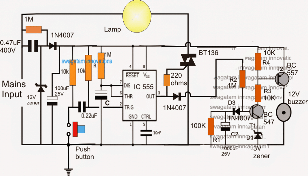
The proposed bathroom lamp timer with prior buzzer alarm circuit is built using a couple of monostable timer circuits, in the form of a IC 555 delay OFF and a transistor based delay ON timer, which are cascaded to function in a sequential manner.
When the timer circuit is powered, the lamp and the buzzer remain inactive however the circuit attains a standby mode.
As soon as the push button is pressed, the IC 555 monostable gets triggered, switching ON the triac and the lamp.
In the meantime, the transistor delay ON timer stage responds to the pin3 trigger of the IC 555 and begins counting, and the moment its set period is lapsed, the buzzer connected with it switches ON.
The above delay ON timer must be set such that it switches ON just before the lamp switches OFF at the desired timer interval.
This can be set with the help of R2 and C2, increasing these increases the delay ON period of the buzzer and vice versa.
For the IC 555 monostable, the time delay OFF for the lamp can be set by appropriately selecting the values of the capacitor C and/or the corresponding 1M resistor.
The entire circuit is powered through a transformerless power supply comprising of a 0.47uF/400 high voltage capacitor, and the associated 12V /1 watt zener and the 100uF/25V capacitor.
THE ENTIRE CIRCUIT IS NOT ISOLATED FROM MAINS AND THEREFORE MAY BE EXTREMELY DANGEROUS TO TOUCH IN SWITCHED ON CONDITION AND UNTIL NOT ENCLOSED INSIDE A SUITABLE INSULATED COVERING.


Questions & Answers
I have tried many of your circuits and all have worked, thanks so you much for your kind efforts and contributions to the world of electronics.
Appreciate it very much.
Thank you so much for your feedback!
Hi mr swag..thanks for your reply..
I mean when the circuit powered, circuit features a delay OFF timer after set 1 or 2 hour time delay (manual), circuit above is great also.
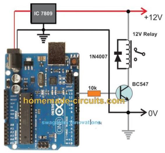
Or can you make a circuit features delay OFF timer after no load (automatic), it can be use for charging all kind devices.
But all with compact size of components (no relay, no dc source, no big components)
Hi Ay,
OK you can try the following circuit for implementing the 1 to 2 hour delay OFF function:
However, the power supply must be given through an SMPS, a transformerless capacitive circuit might not work here.
Ok..thanks mr swag..
Keep the great works..
My pleasure Ay!
Hi mr swag..
Awesome circuit..is there any circuit similar like this who controlling AC power, transformless, no relay & using small components, ???????????????? ???????????? ???????? ???????????????????????? ???????????? ????-???? ???????????????????? ???????? ???????????????? ???????? ????????????????? and need to push the button to activate it again.
Thanks&keep helathy
Thank you Ay,
Can you please elaborate your following statement:
“…???????????????? ???????????? ???????? ???????????????????????? ???????????? ????-???? ???????????????????? ???????? ???????????????? ???????? ?????????????????”
I need more details regarding the above specifications.
hello sir,
What do you mean by “mains input”?
Regards,
It means 230 V or 120 V AC input
Hi,
Hope you and your family are safe and best with your health.
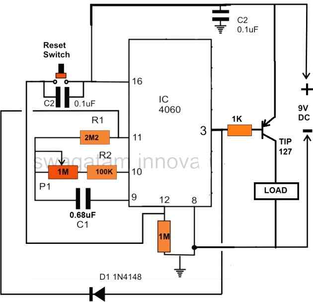
Can you help me with a circuit that auto turn off the light of my bed room after 2 hours once it on. when I go to sleep daily I forget to turn off the light and the light remains on whole night . daily my mom shouted on me ???????????? . I don’t want to add any DC supply with the circuit which continuously consume power. when I switch on the light the circuit should get activate on 220 v and after 2 hours it should get off automatically and if I turn off the power switch the counter get reset and if again I turn on it should on for another 2 hours. hope you understand my requirement. shall be thankful if you can help me.
Regards,
Amit Desai
Hi, You can try the following design:
Please note that this circuit is not isolated from mains and therefore is extremely dangerous to touch in open and powered condition
Hi Swag,
I too looking same kind of circuit. but with some modification,
full circuit has to run by 12V DC
LED Lights 12V 20/30W
Normal on/off switch instead of push button switch. can you suggest me what should I have to modify here.
Regards.
Hi Paaker, you can do the following modifications for accomplishing the mentioned features:
Replace the transformerless power supply with an SMPS 12V 30 watt supply
replace the triac with a mosfet, and wire the LED across the mosfet drain and positive supply line.
replace the push button with a wire link.
replace the 0.22uF capacitor with a 1uF
once done you can switch ON/OfF the SMPS to get the required results.
? will update soon Swag,
OK Great!!
sir i want to make current booter like input 5amp and output will be 16amp
so sir can you sand me reply on ernavneetdholariyaee@gmail .com
Navneet, if you want to boost current then your voltage has to go down at the output….example, if you have 24V/5 amp, if it's boosted to 16 amp, then the 24V will become 7.5V
sir can you send me a list for a component name, because i wish to make this project to be my final project, if you intrested to send please send at decxx97@gmail.com.
DEC, the part name and number are provided in the diagram, please click it to enlarge, all the parts have standard specifications
hello sir,
is it possible to isolate the circuit using SPDT relay to turn on the AC lamp?? can you help me if it possible?
you can increase the input capacitor value to 1uF/400V, and use a 300 ohm (higher will be better) relay across pin3 and ground of IC555
ok thanks, but how much VDC this circuit need if i were going to use the relay?
hello vale, you can connect any two pin switch and connect it across the triac MT1/MT2 leads, this switch will bypass the triac and switch ON the lamp directly whenever required.
hi,
Actually I want to thanking you for all over contribution of yours. Electeonics is my hobby, you don't know how much i learn from your contributions. My stream is biology, and I dont know well about functional aspects of electronics components.
at first when i started i prepared circuits, blindly following the component list and diagram, but now a days I prepare general circuits with understanding, and able to alter the components. I am thanking you actually for this reasons, your ideas and simple descriptions helps lots for me. doing something with understanding boosts confidence also. actually its like a game, when successfully completed one then going to next level of complexity. The major portion of my understanding about making simple circuits is based on your articals, ideas, descriptions etc.
when someone came to my house and found several types of basic electeonics applications and appriciate those things, its makes me happy and I think this success is not only for me, it is also success of yours.
thank you
Biplab,
WB. INDIA
Thank you Biplap, I am glad you could learn through this site and I wish you continue doing this in future also…please feel free to comment anytime you have issues in the relevant field..