In this post I have explained how to make a simple RGB (Red, Green, Blue) LED controller circuit which may be designated to flash a group of RGB LEDs with a particular sequencing pattern. The idea was requested by Mr. Navdeep.
Technical Specifications
I want to make a display board with red, green and blue leds. Approximately 350 each. and i want to use 12 volts rgb controller. please suggest how should i connect LEDs.
I want to light red, green and blue leds separately and then in combinations. And how to make circuit. please also suggest which rgb controller should be used and how it should be connected.
can u suggest a simple circuit for 12 volt 3 amp each, red green blue, rgb controller. with primary colours only.
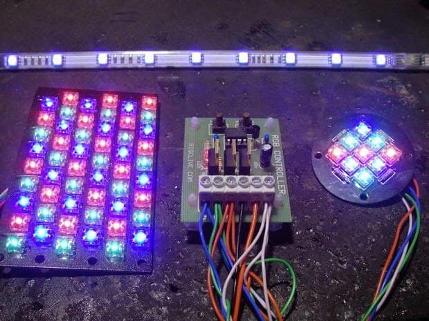
This is the photo of circuit i got from internet. but am not able to understand how to make it help please. please suggest a simple circuit using easily available components. for RGB controller.
The sequence pattern will be: red first, then green, then blue, then red green together. or any order and any combination will do. i just need it for making a led display board. only wish is that leds should light in sequence and combinations.
The Design
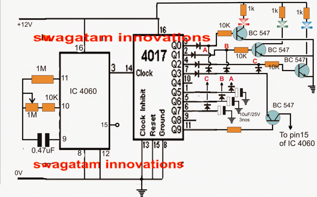
AS per the suggested sequence format, a simple design using a 4017 IC and a 4060 IC can be used for implementing the proposed RGB LED controller circuit.
Referring to the shown diagram, the 4017 IC and the 4060 IC are wired in a standard LED chaser mode, which is also quite popular with the name "Knight Rider" due to its specific running and chasing light effects.
The IC 4060 supplies the clock pulses to the IC 4017 for executing the intended the sequencing of its output pins in response to every clock pulse at its pin14.
However here the output of the 4017 IC is configured a bit differently for implementing a unique RGB flashing pattern.
Here, the red, green blue strings are wired in a special way to achieve the mentioned desired sequencing pattern, that is when switched ON the R, G. B strings first light up in sequence (in a "chasing" like pattern), next all the three strings get illuminated together and shut off, following this next up the three strings light up one after the other without shutting off in the process, and finally the three LED light up together but flash rapidly to finish the sequence.
The cycle then resets and goes back to the initial phase as described in the above explanation.
The 1M pot may be adjusted for getting the desired control and sequencing rate on the RGB LEDs.


Questions & Answers
sir, can we make 12v action chaser (multiple designs) for 12volt single colour pixel led by using ESP32 module?
If yes, then plz send me a circuit diagram for it.
And also codes for the project.
Hi Parth,
I think It will require programming with a code and I am not good with MCU programming, so it might not be possible for me to solve it for you.
Sir,
Hello again my name is Dr.Chris Halgryn and, thank you for all the assistance and suggestions of circuits in the past to date they all were r successful circuits I am very pleased however , I need to ask the circuit where the person need to illuminate 300 RGB leds the schematic shows only (3) three leds…1xred 1xgreen and 1x blue can I connect say only 10 leds in each bank to make (30) leds not necessary 300 leds.
Please advise urgently I would appreciate that at your earliest convenience. Many thanks again,
Dr\.Chris.
Thank you Dr. Chris,
Yes you can use upto 10 LEDs with each transistor in the above circuit by connecting 3 strings of LEDs in parallel, with each string having 4 LEDs in series. Make sure the input voltage is a constant or a fixed 12V from a 7812.
If the LEDs are high power LED then the transistors will need to be upgraded to TIP122.
Please let me know if you have any further questions.
I want to light my walkway between the carport and the front porch using ir motion sensors to one set of 4 50 cm (or mm) LEDs they would be approximately 20 inches each. Then another ir sensor and another set of LEDs and so on until have 5 sets. How ever I want to make them work from the porch to the carport also.
Using 12 V source each way. By the way I am the NW part of Oregon, USA
I think you can install the 2) concept presented in the following article for your requirement:
https://www.homemade-circuits.com/pir-motion-activated-relay-circuit/
great circuit could the outputs be switched positive ? what would the final stage look like for say 3x3amp common ground .. thanks
Glad you liked it, yes the output can be switched positive by adding additional PNP transistors with the BC547 transistors and then connecting the RGB LEDs across their collectors.
Please Sir, the RGB driver is a remote control with each button controlling different lights.what ic is implemented in such a design because i managed to buy one , after carefully exposing the board,there were three scr’s with each label 2P4m , with resistors connected to one side of each scr and Connected to separate pins of the ic .The ic number was not labelled and no number at all was written on top or beneath it.Please Sir, could you help me identify such ic number or the type of ic being used?I saw that the ic was having four pins on each side just like the ne555 timer pin configuration.
Lawal, it can difficult to find out the actual working of the circuit without knowing the datasheet of the IC
The diodes used in this circuit,are they 1N4148? Also can i use any lower value capacitor instead of .47uf?
yes 1N4148 is OK, the 0.47uF is the timing capacitor, lower values may decrease the range of sequencing rate of the IC 4017
Thanks..for your regular support..
can I use 5 LEDs (20mA) or more in each output and wat changes should I supposed to make?
5 leds is an odd figure, use 6 instead, make strings of 3 in series, and connect two such strings in parallel with each transistor. replace 1K with 330 ohms and use this on each string:
Hello Sir !!!
i want to use above circuit with 9v battery .will i need 6 ohm 1 watt resistances then ?
i will be using 1 watt leds,TIP122
Hello asif,
you'll need:
9 – 3.3 / 0.3 = 19 ohms or 18 ohm resistor having 3.3 x 0.3 = 0.99 or 1 watt
hi swagatam
thanks for reply
for the ic 4060 i connect a led to pin no 3 which gives pulses to ic 4017 its always zero and no led glows
Hi Samaj,
that means your 4060 is not working or is faulty…
LED should be between pin3/pin14 and ground….with a 1K resistor.
hellow swagatam
is it 100% working as per rgb controller circuit request by navdeep
because of when i start power supply that time only one led glow and after surtain interval i assume second led glow but its cant
and circuit cross checked with circuit diagram
any idea
hello samaj, is your IC4060 providing the required clock pulses to pin14 of the 4017 IC?
confirm this by connecting an LED across pin14 of 4017 and ground, with a 1K resistor in series….this LED should flash at an approximately 1Hz rate….
if this happens only then the RGB would respond as per the proposed specs.
Hell Sir
Can i use 1W three R,G,B LED in this circuit what changes I have to make
Hello Sandeep, yes you can do it, use TIP 122 for the transistors, and connect 3 LEDs in series across the relevant collectors of the transistors…make sure the each LED string has a 6 ohm 1 watt resistor in series.
Hello sir u got the circuit for pixel led
Hello Basit, the LED effect shown in your video clip won't be possible with a simple circuit, it will require a microcontroller based circuit…it looks very complicated so won't be possible at my level…still I'll try to figure it out…
Hello sir I have email you on your id about pixel led so pls check it
Thanks
Hello sir u got the circuit for pixel led………
Eagerly waiting for the circuit….. Sir thanks
no not yet, I am still trying
Ok sir so u have any circuit for this pixel led I want to run 6 strings of 50 leds in parallel each
I have no idea about the "data" input to be fed to a RGB pixel string, i'll investigate, if it's just ordinary clock sequence then probably I'll try to produce a suitable circuit for you.
Ok sir so u have any circuit for this pixel led
Hello sir I have pixel led of
Model No:RGB 12mmToo-ICA
Color – full color
Size – 12mm
Power – 0.3watt
And it contain 50 leds string
So can I use above circuit for this leds
Hi Basit, 50 LED series cannot be used in the above shown circuit transistors, because 50 LEDs in series would require 50 x 3.3 = 165volts…that's too high for any standard general purpose transistor
There must be an error somewhere, when Q0 is 1 all other are 0, so Q0 will feed Q5 etc..
No LED should be lit !
thanks, please check it now
No, not possible to get the code. they are bussinessman.
one more thing they have used PIC preprogrammed. In our case we dont know / cannot programme it.
Dear Navdeep, if it's possible to get the code I'll update the info in the article for your reference.
Dear Swagatam,
RGB controller shown above in photo also has all above functions. Components used in that controller are one zener to supply 5 volt contant supply to controller chip, one 10,000 ohm resistor, one 1A rectifier diode, onen socket for the chip, one SIL (Single In Line) resistor array. This component has eight pins and has four serparate 1000 ohm resistors in it, one decoupling capacitor, two control buttons, three MOSFET transistors, one chip PIC12F629 microcontroller.
This information i could get from internet. but circuit diagram is not given and plate has to ordered from outside india.
Dear swagatam,
i wanted a circuit that could do following functions.
Product Description:
Supply voltage:12V
Output:Three CMOS drain- open output
Output current:<4A(each channel)
Output power:<144W
Connecting Mode:Common anode
https://drive.google.com/file/d/0B1yh2zqFOUHZR0RjanpFZTJqT00/view?usp=sharing
https://drive.google.com/file/d/0B1yh2zqFOUHZdG8xUV9LRmROV0E/view?usp=sharing
https://drive.google.com/file/d/0B1yh2zqFOUHZYXd2OXlqVzZoa00/view?usp=sharing
Dear Swagatam, i dont need a separate remote. buttons can be placed on same plate circuit. This circuit will be useful for making LED boards that u must have seen outside hotels and hospitals with red, green and blue leds. In this circuit we can choose which colours we want.
thank u for your kind support.
…OK I think it's given in your second diagram, let me think, If it' possible i'll update it here.
Dear Navdeep,
I dd not understand the application, please explain how the entire system is opposed to function.
can i use ic 555 instead of ic 4060.
555 can be used but it won't give you the last feature at pin11 from IC 4017….
Dear Swagatam,
thanks for your quick response. i have few queries. If i connect 12 volt 12 ampere supply to input, can i put a load of 3 – 4 ampere on each red, green and blue string.
Dear Navdeep, yes it is possible but the transistor will need to be upgraded accordingly, you may need a TIP142 for this.
hi swagatam,
can we use 9v battery with this circuit ?
Hi Bibin, you can use any voltage between 4.5V and 15V