When you want to light up a large garden path, then a farmhouse entrance, or a remote colony road where electricity bill and AC wiring are out of the question, a high wattage solar system is the ultimate solution. Today we will investigate how to build a robust 40W solar street light featuring automatic night detection, smart battery charging and high efficiency LED driving.
Main Purpose to Build a High Power Solar Street Light
Standard low power garden lights only give a dim glow but a true 40W solar street light needs serious engineering.
It must handle high solar panel current during scorching daylight heat, protect your expensive 12V storage battery from getting overcharged or deeply discharged and deliver steady, regulated current to a massive array of high power white LEDs all night long.
This complete circuit integrate solar regulation, LDR dusk to dawn switching and transistorized high current driving into one single unit.
LED Lamp Specifications
- Voltage: 12 volts (12V/26AH Battery)
- Current Consumption: 3.2 Amps @12 volts,
- Power Consumption: 39 watts by 39nos of 1 watt LEDs
- Light Intensity: Approximately around 2000 lm(lumens)
Charger/Controller Specification
- Input: 32 volts from a solar panel specified with around 32 volts open circuit voltage, and short circuit current of 5 to 7 Amps.
- Output: Max. 14.3 volts, current limited to 4.4 Amps
- Battery Full - Cut OFF at 14.3 volts (set by P2).
- Low Battery - Cut OFF at 11.04 volts (set by P1).
- Battery charged at C/5 rate with float voltage restricted to 13.4 volts after “battery full cut OFF”.
- Automatic Day/Night Switching with LDR Sensor (set by selecting R10 appropriately).
Detailed Circuit Analysis
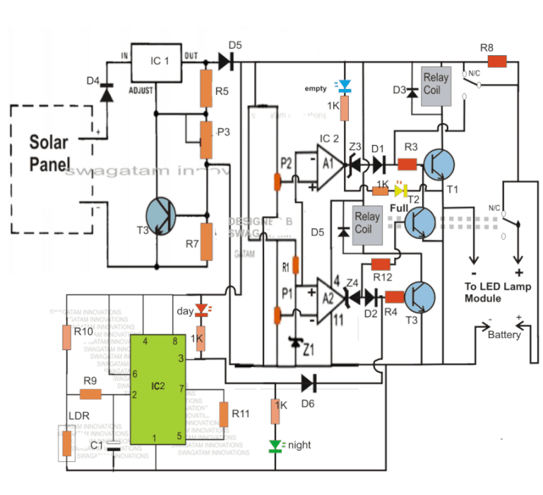
In this first part of the article we will study the solar charger/controller stage and the corresponding over/low voltage cut-off circuit, and also the automatic day/night cut-off section.
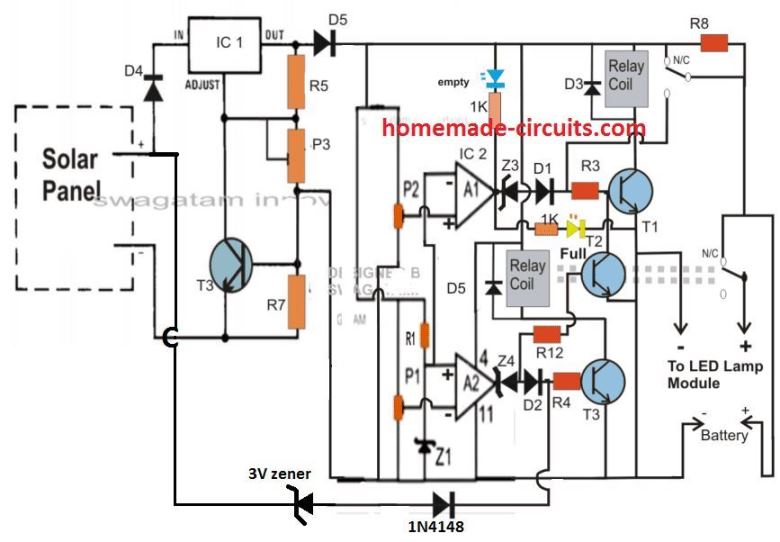
The above design can be much simplified by eliminating the IC 555 stage and by connecting the day time relay cut OFF transistor directly with the solar panel positive, as shown below:
Parts List
- R1, R3,R4, R12 = 10k
- R5 = 240 OHMS
- P1,P2 =10K preset
- P3 = 10k pot or preset
- R10 = 470K,
- R9= 2M2
- R11 = 100K
- R8=10 OHMS 2 WATT
- T1----T4 = BC547
- A1/A2 = 1/2 IC324
- ALL ZENER DIODES = 4.7V, 1/2 WATT
- D1---D3,D6 = 1N4007
- D4,D5 = 6AMP DIODES
- IC2 = IC555
- IC1 = LM338
- RELAYS = 12V,400 OHMS, SPDT
- BATTERY = 12V, 26AH
- SOLAR PANEL = 21V OPEN CIRCUIT, 7AMP @SHORT CIRCUIT.
Solar Charger/Controller, High/Low Battery Cut OFF and Ambient Light Detector Circuit Stages:
CAUTION: A charge controller is a must for any street light system. You may find other designs on the internet without this feature, simply ignore them. Those can be dangerous for the battery!
Referring to the 40 watt street light circuit diagram above, the panel voltage is regulated and stabilized to the required 14.4 volts by the IC LM 338.
P3 is used for setting the output voltage to exactly 14.3 volts or somewhere near to it.
R6 and R7 forms the current limiting components and must be calculated appropriately as discussed in this solar panel voltage regulator circuit.
The stabilized voltage is next applied to the voltage/charge control and the associated stages.
Two opamps A1 and A2 are wired with converse configurations, meaning the output of A1 becomes high when a predetermined over voltage value is detected, while the output of A2 goes high on detection of a predetermined low voltage threshold.
The above high and low voltage thresholds are appropriately set by the preset P2 and P1 respectively.
Transistors T1 and T2 respond accordingly to the above outputs from the opamps and activates the respective relay for controlling the charge levels of the connected battery with respect to the given parameters.
The relay connected to T1 specifically controls the overcharge limit of the battery.
The relay connected to T3 is responsible for holding the voltage to the LED lamp stage. As long as the battery voltage is above the low voltage threshold and as long as no ambient light is present around the system, this relay keeps the lamp switched ON, the LED module is instantly switched OFF in case the stipulated conditions are not fulfilled.
Circuit Operation
IC1 along with the associated parts forms the light detector circuit, its output goes high in the presence of ambient light and vice versa.
Assume it's day time and a partially discharged battery at 11.8V is connected to the relevant points, also assume the high voltage cut off to be set at 14.4V. On power switch ON (either from the solar panel or an external DC source), the battery starts charging via the N/C contacts of the relay.
Since it's day, the output of IC1 is high, which switches ON T3. The relay connected to T3 holds the battery voltage and inhibits it from reaching the LED module and the lamp remains switched OFF.
Once the battery gets fully charged, A1's output goes high switching ON T1 and the associated relay.
This disconnects the battery from the charging voltage.
The above situation latches ON with the help of the feedback voltage from the N/O contacts of the above relay to the base of T1.
The latch persists until the low voltage condition is reached, when T2 switches ON, grounding T1's base biasing and reverting the top relay into the charging mode.
This concludes our battery high/Low controller and the light sensor stages of the proposed 40 watt automatic solar street light system circuit.
The following discussion explains the making procedure of the PWM controlled LED module circuit.
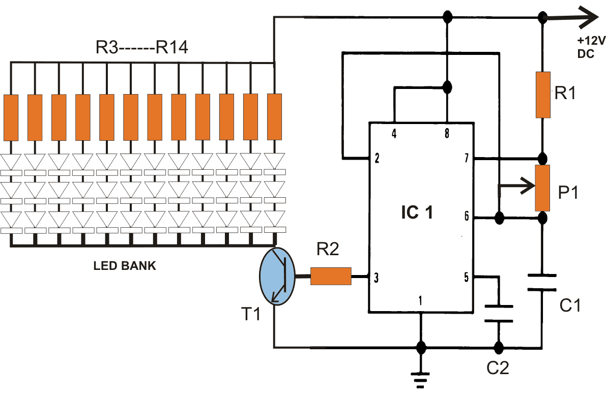
The circuit shown below represents the LED lamp module consisting of 39 nos. 1 watt/350 mA high bright power LEDs.The whole array is made by connecting 13 number of series connections in parallel, consisting of 3 LEDs in each series.
How it Works
The above arrangement of LEDs is pretty standard in its configuration and does not focus much importance.
The actual crucial part of this circuit is the IC 555 section, which is configured in its typical astable multivibrator mode.
In this mode the output pin#3 of the IC generates definite PWM wave-forms which can be adjusted by setting the duty cycle of the IC appropriately.
The duty cycle of this configuration is adjusted by setting P1 as per ones preference.
Since the setting of P1 also decides the illumination level of the LEDs, should be done carefully to produce the most optimal results from the LEDs. P1 also becomes the dimming control of the LED module.
The inclusion of the PWM design here plays the key role as it drastically reduces the power consumption of the connected LEDs.
If the LED module would be connected directly to the battery without the IC 555 stage, the LEDs would have consumed the full specified 36 watts.
With the PWM driver in operation, the LED module now consumes about 1/3rd power only, that is around 12 watts yet extracts the maximum specified illumination from the LEDs.
This happens because, due to the fed PWM pulses the transistor T1 remains ON only for 1/3rd of the normal time period, switching the LEDs for the same shorter length of time, however due to persistence of vision, we find the LEDs to be ON all the time.
The high frequency of the astable makes the illumination very stable and no vibration can be detected even while our vision is in motion.
This module is integrated with the previously discussed solar controller board.
The positive and the negative of the shown circuit needs to be simply connected to the relevant points over the solar controller board.
This concludes the whole explanation of the proposed 40 watt automatic solar LED street lamp circuit project.
If you have any questions, you may express them through your comments.
UPDATE: The above theory of seeing high illumination with lower consumption due to persistence of vision is incorrect. So sadly this PWM controller only works as a brightness controller and nothing more!
Circuit diagram for the street light LED PWM controller
Parts List
- R1 = 100K
- P1 = 100K pot
- C1 = 680pF
- C2 = 0.01uF
- R2 = 4K7
- T1 = TIP122
- R3----R14 = 10 Ohms, 2watt
- LEDs = 1 watt, 350 mA, cool white
- IC1 = IC555
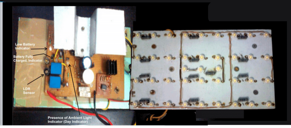
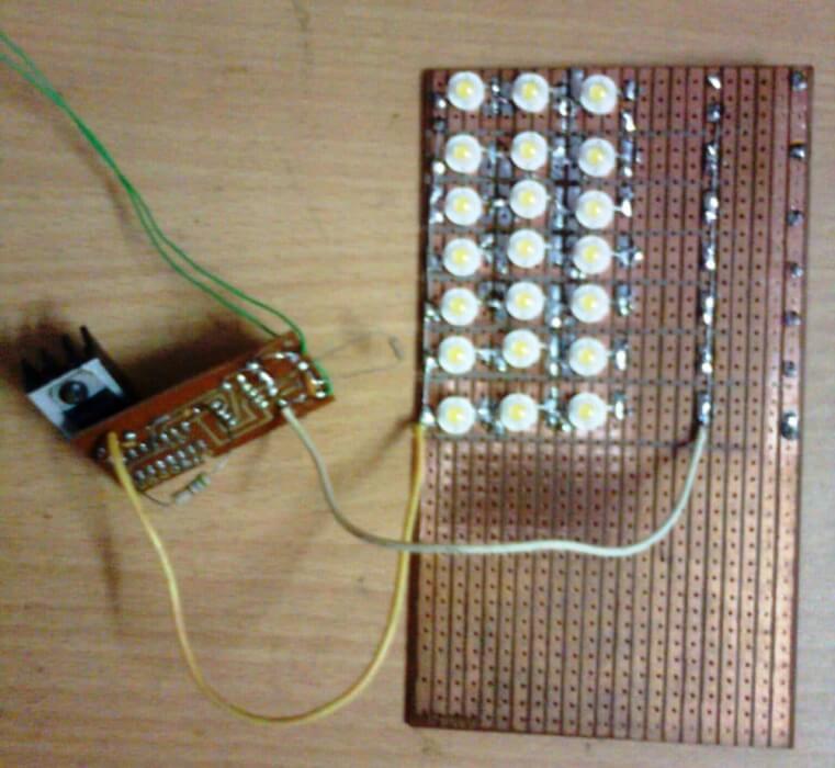
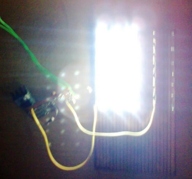
In the final prototype the LEDs were mounted on special aluminum based heatsink type PCB, it is strongly recommended, without which the LED life would deteriorate.
Prototype Images
Troubleshooting and Fault Finding Tips
Battery is Not Charging During the Day:
Cause: The solar reverse blocking diode is connected backward, or your solar panel is kept in a shady area where tree leaves or building shadows fall on it.
Solution: Check polarity of blocking diode. Clean the glass of your 20V solar panel and place it directly under open sky facing south (or maximum sunlight direction) so it receive full day sun.
LEDs are Flickering or Dimming Rapidly at Night:
Cause: Your 12V battery voltage has dropped too low because of cloudy weather, or the LED current limiting resistors (7 ohm, 2W) are getting excessively hot and changing resistance.
Solution: Disconnect the system and charge your battery fully using a normal wall charger to check if the battery holds backup then. Also check if your sery parallel resistors is rated properly for 2 watt or higher so they do not overheat then.
TIP142 Transistor is Getting Extremely Hot or Burning Out:
Cause: A 40 watt LED array draws around 3 to 4 Amps of high current. If you bolted TIP142 transistor directly to the circuit board without an aluminum heatsink, then it will overheat and get spoilt.
Solution: Always mount the TIP142 transistor on a thick aluminum heatsink using thermal paste. Check your LED wiring to make sure there are no partial short circuits increasing current draw.
LED Stay ON Even During Bright daylight:
Cause: LDR sensor is placed in a dark corner or under a shed where sunlight cannot touch it properly, keeping pin 2 of the 555 IC permanently low.
Solution: Relocate your LDR so it faces the open sky directly. Adjust the 1M preset slowly in the opposite direction until the 555 IC output flips to low and shuts off the TIP142 transistor under bright sun.
Battery Drains Out Completely Within 1 or 2 Hours:
Cause: Your storage battery has become old and lost its Amp hour (Ah) capacity, or you are trying to run a heavy 40W load on a very small battery (like a 7Ah UP battery instead of a 40Ah/50Ah deep cycle battery).
Solution: Make sure you are using in least a 12V, 40Ah or 50Ah rechargeable battery for a heavy 40 watt LED street light setup so it can easily give you backup for 8 to 10 hours through the night.



Need Help? Please Leave a Comment! We value your input—Kindly keep it relevant to the above topic!