In one of our earlier article, we learned how to build automatic street light circuits using single and double transistors, an IC 555 timer and a solar panel setup.
Today we are going to investigate another design from our collection which uses famous IC 741 operational amplifier as a precision voltage comparator.
If you are a student, then engineering hobbyist, or DIY lover who wants to learn how op amp work in real world control circuit, this IC 741 light sensor project is a fantastic and educational build.
Why the Versatile IC 741 works so good in a Street Light Circuit?
An operational amplifier (op amp) like the 741 is specially designed to compare two voltage level.
When you use a simple transistor, then the switching point can sometimes shift with temperature or component aging.
But when you use an IC 741 configured as a differential voltage comparator, then it compares the voltage drop across your LDR divider network against a fixed reference voltage set by a preset potentiometer.
This gives very stable performance and allows you to tune the light detection threshold with great precision.
Bill of Materials
To build this IC 741 automatic street light circuit, you will need the following electronic components:
- IC1 = 741 Operational Amplifier IC (with an 8-pin IC base socket)
- LDR1 = Standard Light Dependent Resistor (LDR)
- P1 = 10K or 100K preset potentiometer (used for setting light sensitivity threshold)
- Resistors = 1K, 10K, and 47K resistors (1/4 watt, 5% CFR)
- C1 = 100uF / 25V electrolytic capacitor (for power supply filtering)
- D1 to D4 = 1N4007 diodes (for the AC bridge rectifier)
- D5 = 1N4007 diode (used as a flyback protector across the relay coil)
- T1 = BC547 NPN transistor (used to drive the relay)
- TR1 = 0-12V, 500mA or 1 Amp step-down transformer (or you can use a ready-made 12V SMPS adapter)
- RL1 = 12V relay (200 to 400 ohm coil resistance)
- LED Bulb = 220V or 120V LED bulb (100 watt or as per your street light requirement)
Warning Regarding AC Mains
Kindly remember that this circuit control a high voltage AC main bulb (220V or 120V) through the relay contact. Working with AC power is very dangerous and can cause severe electric shocks or fatal accidents if proper care is not taken then.
Always keep the power disconnected while soldering or making wiring changes, use insulated tools and enclose the final circuit safely inside a well insulated plastic junction box so that no bare AC wires are left exposed outside.
Circuit Diagram
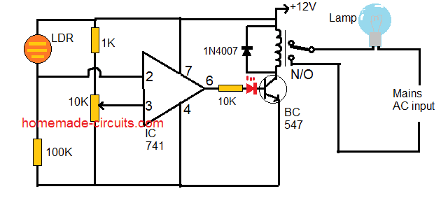
Working Description
The working of this op amp circuit is based on voltage comparison:
Comparator Setup: The IC 741 is powered using a single 12V supply (Pin 7 goes to +12V and Pin 4 goes to Ground). LDR and preset form a voltage divider network connected to the input pins of the op amp.
During Daytime: When bright sunlight fall on the LDR, then its resistance is very low. This changes the voltage at op amp input terminal compared to the reference voltage set by preset P1. As a result, the output in Pin 6 of the IC 741 goes LOW.
When Pin 6 is low, then transistor T1 stay turned OFF, the relay is de energized and your street light bulb remains switched OFF.
During Nighttime: When evening arrive and ambient light decreases, then the LDR resistance goes very high. This shifts the input voltages on the op amp. As soon as the LDR voltage crosse the reference voltage set by the preset, IC 741 output at Pin 6 flips instantly to HIGH.
Relay Activation: When Pin 6 goes high, then it supplies base current to transistor T1, turning T1 ON. So now the relay clicks and activate, shifting it switch contact to complete the AC circuit and your street light bulb turns ON automatically.
In-Depth Working Description
Here the IC 741 is designed as a comparator, wherein its non-inverting pin#3 is connected to a 10k preset or pot for creating a triggering reference at this pinout.
Pin#2 which is the inverting input of the IC is configured with a potential divider network made by a light dependent resistor or LDR and a 100K resistor.
The 10K preset is initially adjusted such that when the ambient light on the LDR reaches to the desired darkness threshold, the pin#6 goes high. This is done with some skill and patience by moving the preset slowly until pin#6 just goes high, which is identified by the switching ON of the connected relay and the illumination of the red LED.
This must be done by creating an artificial darkness threshold light level on the LDR inside a closed room and by using dim light for the purpose.
Once the preset is set, it may be sealed with some epoxy glue so that the adjustment remains fixed and unchanged.
After this the circuit may be enclosed inside a suitable box with a 12V adapter for powering the circuit, and the relay contacts wired with the desired road lamp.
Care must be taken to ensure that the lamp illumination never reaches the LDR, otherwise it may lead a continuous oscillations or flickering of the lamp as soon as it is triggered at twilight.
Pinout Reminder IC 741 Pin Connections
Be very careful when inserting 741 IC into its holder then. Pin 2 is the Inverting input, Pin 3 is the Non inverting input, Pin 6 is the Output, Pin 4 goes to Ground (Negative) and Pin 7 goes to the +12V positive supply line.
Reversing power pins can damage the IC instantly.
Relay Flyback Diode: Rememeber diode D5 (1N4007) is connected in reverse bias across the two coil terminals of your 12V relay.
This freewheeling diode absorbs high voltage back EMF spikes when the relay turns off, then protecting transistor T1 from burning out.
Step by Step Setup and Calibration
- After you solder all components carefully on your PCB or general board, follow these simple step to set it up:
- Plug your 12V power supply into the circuit's input rails.
- Point the LDR in the kind of light you would see in the evening, or put your hand over it to make it feel like dusk.
- Turn preset potentiometer P1 very carefully until you hear the relay make a clicking sound and your 220V LED bulb light up.
- Take your hand away so regular room light hits the LDR and the bulb should shut off right away.
- After you have got it working just right, put a tiny bit of glue or nail polish on the preset knob so it stay in place and does not move from wind or shaking.
Troubleshooting Tips
Relay is Clicking or Blinking Continuously in Evening:
Cause: Optical feedback. If light from your controlled street bulb falls directly onto the LDR sensor, then circuit get confused, thinking day has returned, turning off lamp and creating an continuous blinking loop.
Solution: Always mount your LDR facing upward toward the open sky or inside a small dark plastic visor/shield so that light from the street bulb can never touch the LDR surface.
Bulb Stays ON Even in daylight:
Cause: Preset P1 is adjusted incorrectly, keeping the op amp output high even under bright light.
Solution: Expose LDR to bright sunlight and adjust preset P1 in the opposite direction until the IC 741 output at Pin 6 goes low and the relay release.
Relay Makes a Buzzing Sound:
Cause: Weak power supply or low voltage from your 12V transformer/SMP adapter.
Solution: Make sure your 12V power supply can provide a steady current of at least 500mA to 1 Amp and check filter capacitor C1 (100uF/25V).
So guys, we end here....if you do exactly as given in this simple guide, you can successfully build your own precision IC 741 automatic street light circuit for your home or outdoor gate.




Need Help? Please Leave a Comment! We value your input—Kindly keep it relevant to the above topic!