We learned how to make automatic street light circuits using a single transistor and an IC 555. But what will you do if there is no AC mains electricity near your village road, then farm house, or outdoor gate?
For such places where 220V power is not available, a solar powered automatic street light is the best solution.
Today we are going to learn how to build a compact 24W solar street light system that charges its battery during daytime using solar power and automatically turns on bright LEDs at night.
Thee Advantage of Solar Street Light Circuit?
Many time people want to put street light in open places where running long AC power cables is very difficult and expensive.
By using a solar panel, a 12V rechargeable battery and an automatic LDR sensor circuit, you get a completely independent outdoor lighting system.
It does not take any electricity from your home meter, it has zero electricity bill and it works automatically every single day without any manual headache.
Required Parts List
To build this solar street light controller circuit, you will need the following electronic components:
- Solar Panel = 20V, 4 Amp solar panel (for charging battery during day)
- Battery = 12V, 25 Ah rechargeable lead-acid or lithium battery (for night backup)
- IC1 = NE555 timer IC (used as light sensor comparator)
- IC2 = LM338 adjustable voltage regulator IC (used for safe battery charging control)
- T1 = TIP142 NPN Darlington power transistor (used to drive high power LEDs)
- LDR = Standard Light Dependent Resistor (for night detection)
- R1 = 1M preset potentiometer (for adjusting light trigger sensitivity)
- R2 = 1M resistor (1/4 watt)
- R3 = 875 ohms (or simply 1K resistor, 1/4 watt or higher, connected to transistor base)
- R4 = 100K resistor (1/4 watt)
- R13 = 150 ohms resistor (1/4 watt)
- R14 = 15K resistor (1/4 watt)
- R15 = 33 ohms resistor (1/4 watt)
- LED Series Resistors (R5 to R12) = 7 ohms, 1 watt resistors (calculated for LED current control)
- All LEDs = 1-watt, 3.3V high-bright white power LEDs (connected in series-parallel groups)
Important Safety & Wiring Warning
Working with solar panels and high capacity 12V batteries requires care. Always connect your battery and solar panel with correct polarity (Positive to Positive, Negative to Negative).
Reversing battery wires can instantly damage your voltage regulator IC or burn components. Also make sure your wire thickness is good enough to handle LED and charging currents without heating up.
Circuit Diagram
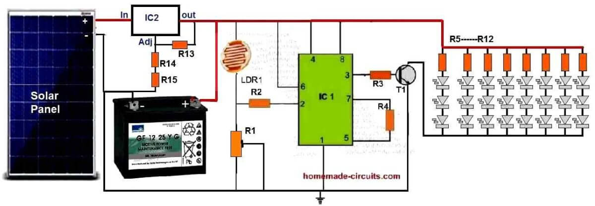
Solar Street Light Circuit Basic Working
This solar street light system has two main parts working together: the solar charging section and automatic light sensor switching section.
Solar Battery Charger Section: During daytime, when bright sun fall on 20V 4A solar panel, then it generates electrical power.
This power goes into an LM338 adjustable voltage regulator circuit. Resistor values on the LM338 are carefully chosen so that output charging voltage never goes above 14. 1V. This prevents your 12V battery from getting overcharged and keeps it safe for a long life.
Day and Night Sensor Section: Just like our IC 555 circuit, the IC1 timer is wired as a comparator. During daytime, sunlight falls on the LDR, making its resistance very low. This keeps pin 2 of the 555 IC high which keeps the output at pin 3 low.
When output pin 3 is low, then the TIP142 Darlington transistor remain switched OFF and all the high power LEDs stay turned off during the day while the solar panel charges the battery.
Automatic Night Switch ON: When evening comes and darkness starts, then LDR resistance goes very high.
This pulls pin 2 of the 555 IC down to ground level through preset R1. The IC output at pin 3 immediately become positive which supplies base current to heavy duty TIP142 transistor.
LED Lighting Section: As soon as transistor TIP142 turns ON, current flows from the 12V battery through all the series parallel white LEDs. So now the LEDs start glowing brightly at dusk, lighting up your pathway or street.
When morning comes again, then the LDR detect sunlight, flips the 555 IC output back to low, turns off transistor T1 and the LED turn off automatically while solar charging start again.
Detailed Working Analysis
As described in the previous section, the IC 555 is configured like a comparator. During day time when light level is high on the LDR, pin#2 potential held towards the positive level which causes the pin#3 output to be low and the transistor T1 to remain shut off.
With T1 shut off, all the LEDs also remain shut off during the day time.
At night when the light level drops on the LDR, its resistance increases causing a ground potential to develop on the pin#2 of the IC 555 via R1.
This instantly reverts the pin#3 situation and it becomes positive, which turns ON the transistor T1.
When T1 turns ON, the LEDs all light up at dusk illuminating the passage where it is installed, and effectively serving the purpose of an automatic street lamp circuit.
A solar panel is used to charge a battery via a simple LM338 based voltage regulator.
The resistor values selected for the LM338 circuit ensures that the voltage to the battery never exceeds 14.1V thus make sure that the battery can never over charge.
During day time the solar panel charges the battery to an optimal level. At night the battery delivers the required back up to illuminate the LEDs.
Relay Connection Details
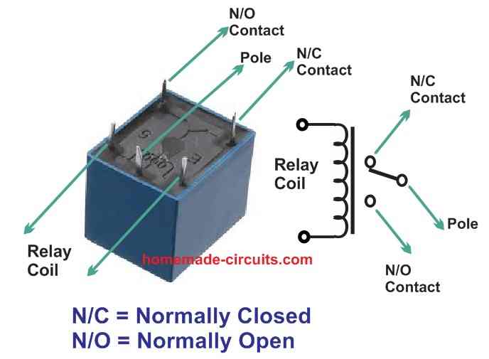
If you are new to electronics and are confused with the relay connections shown in the schematics, then the following figure will help you to understand it quickly.
The diagram compares the schematic symbol of the relay with an actual relay pin image and clearly indicates which parts of the symbol represent which pinout of the actual relay.
Important Calculations for LED Resistors
In this circuit, we are using 1 watt high bright white LEDs that require around 3. 3V each.
If you connect them in series parallel groups across a 12V battery, then you need to use series resistors (R5 to R12) to control the current.
The formula used is:
R = (Supply Voltage Total LED Voltage) / LED Current
For example, if your supply is 12V and your series LED drop is 9 then. 9V at 0. 3A current, the resistor value comes to around 7 ohm, rated in 1 watt so it does not get hot.
Step by Step Setup and Calibration Guide
First connect your solar panel to the LM338 charging input stage and check with a multimeter that the output voltage going to the battery is around 14.1V maximum, connect your 12V battery to circuit power rails.
Replace or adjust preset R1 while covering the LDR with your hand to simulate evening time.
Next, adjust the preset slowly until the TIP142 transistor turn on and your LED array lights up brightly.
Remove your hand from the LDR to let room light fall on it and LEDs should turn OFF instantly.
Fix the preset position with a drop of glue so it does not shake loose.
Troubleshooting Tips for Solar Street Light Controller Circuit
Battery is Getting Overheated or Boiling:
Cause: The LM338 voltage regulator is not set properly, allowing too much charging voltage (above 14. 2V) from the solar panel into the battery...
Solution: Disconnect the battery immediately.
Measure charging output voltage across the LM338 terminals with a digital multimeter while the solar panel is in bright sun.
Adjust the preset/resistors on LM338 until maximum voltage stop strictly at 14, 1V.
LEDs Stay ON During Daytime:
Cause: The LDR is wired incorrectly, or preset R1 is set too high so that even bright sunlight cannot pull pin 2 of the 555 IC high.
Solution: Check your LDR and R1 connections. Adjust preset R1 in the opposite direction while exposing the LDR to bright sunlight until the 555 IC output goes low and turns off the TIP142 transistor.
LEDs are Too Dim or Battery Die Very Quickly at Night:
Cause: Your battery capacity is too low, or solar panel is not getting enough direct sunlight during the day to fully charge the 25 Ah battery.
Solution: Check if your solar panel is placed in a shadow free outdoor spot then. Also check the series resistors (R5 to R12) on your LED to make sure they is not too high which would restrict the LED brightness.
So Guys, that's all here, by following this simple guide, you can successfully build your own off grid solar street light controller circuit and light up any dark outdoor area without electricity bills.




Need Help? Please Leave a Comment! We value your input—Kindly keep it relevant to the above topic!