• Skip to main content
  • Skip to primary sidebar

Homemade Circuit Projects

Need circuit help? Post them in the comments! I've answered over 50,000!

Blog | Categories | About | Hire Me | Contact | Calculators-online
You are here: Home / Lamps and Lights / Joule Thief Circuit which can Illuminate any 3.3V LED or Higher

Joule Thief Circuit which can Illuminate any 3.3V LED or Higher

Last Updated on October 30, 2026 by Swagatam Leave a Comment

The concept discussed here remains exactly identical to the usual joule thief configuration, we just replace the  normally used 5mm LED with a 1 watt LED.

Table of Contents
  • Parts List
  • How the Circuit Functions
  • Video Demonstration
  • How to wind the Torroid Coil

Of course this would mean the battery getting drained pretty much earlier than a 5mm LED, but it's still economical than using a two 1.5 cells and not including a joule thief circuit.

Let's try to understand the proposed circuity with the following points:

If you see the circuit diagram the only seemingly difficult part is the coil, rest of the parts are just too easy to configure. However if you have a suitable ferrite core and some spare thin copper wires, you would make the coil within minutes.
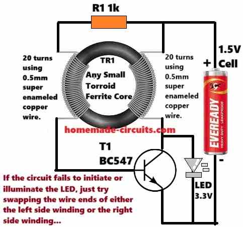
simple joule thief pictorial diagram for illuminating a 3.3V LED using a 1.5V battery

The above design may be improved further by attaching a rectifying network using a diode and a capacitor, as shown below:
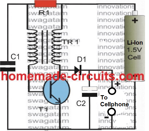
simple joule thief schematic diagram for illuminating a 3.3V LED using a 1.5V battery

Parts List

  • R1 = 1K, 1/4 watt
  • C1 = 0.0047uF/50V
  • C2 = 1000uF/25V
  • T1 = 2N2222
  • D1 = 1N4007 better if BA159 or FR107 is used
  • Coil = 20 turns each side using 1 mm enameled copper wire over a ferrite ring which accommodates the winding comfortably

The coil may be wound over a T13 torroidal ferrite core using a  0.2mm or 0.3mm super enameled copper wire. About twenty turns on each side will be quite enough. In fact any ferrite core will, a ferrite rod or bar will also serve the purpose well.

After this is done, its all about fixing the parts in the shown manner.

If everything is done correctly, connecting a 1.5 V penlight cell would instantly illuminate the attached 1 watt LED very brightly.

If you find the circuit connections to be alright yet the LED not illuminating, just interchange the coil winding terminals (either the primary ends or the secondary ends) this would fix the problem immediately.

How the Circuit Functions

When the circuit is switched ON, T1 receives a biasing trigger via R1 and the associated primary winding of TR1.

T1 switches ON and pulls the entire supply voltage to ground and in the course chokes the current across the primary winding of the coil so that the biasing to T1 dries up, shutting off T1 instantaneously.

The above situation switches OFF the voltage across the secondary winding triggering a reverse emf from the coil which is effectively dumped across the connected LED. The LED illuminates!!

However the shutting of T1 instantaneously also releases the primary winding and restores it to original condition so that the supply voltage now can pass across to the base of T1. This initiates the whole process yet again and the cycle repeats at a frequency of around 30 to 50 kHz.

The connected LED also illuminates at this rate, however due to the persistence of vision we find it illuminated continuously.

Actually the LED is ON only for 50 percent of the time period, and that's what makes the unit so economical.

Also because TR1 is able to generate voltages that may be many times greater than the supply voltage, the required 3.3V to the LED is sustained even after the cell voltage has dropped to about 0.7V, keeping the LED well illuminated even at these levels.

Video Demonstration

How to wind the Torroid Coil

The torroidal coil can be built according to the following steps:

Take a super enameled copper with, maybe around 0.5mm, thickness of the wire is not criticaal, it simply decides its maximum capacity to handle the load current. For our application, 0.5mm looks good enough.

Wind two 20 turns of winding on the core, as shown in the following diagram:
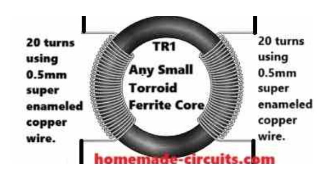
Don't worry about the winding polarity, meaning the direction of the winding, whether clockwise or anticlockwise...don't worry about it, just complete the winding as shown in the above figure.

If suppose the LED fails to illuminate, or the circuit fails to oscillate, you just have to swap the winding terminals of either side of the winding connection with the circuit, but not both sides, swap any one side winding terminals.

For example, suppose you connect the coil upper side terminal with the R1 (1k) and lower side terminal with the transistor base, and you find the circuit is not working, now you just have to interchange the winding terminals....meaning connect the terminal which was connected to R1, with the T1 base, and connect the base winding terminal, with R1....got it?

You'll also like:

  • Difference Between Forward Converter and Flyback Converter
  • simplestrobelightcircuitLED Strobe Light Circuit with Chasing, Flashing Effects
  • stairway light automaticSound Activated LED Lamp Circuit
  • Flashlight Circuit with Long Backup and High Efficiency

Filed Under: Lamps and Lights, SMPS and Converters Tagged With: Higher, Illuminate, Joule, LED, Thief

About Swagatam

I am an electronics engineer and doing practical hands-on work from more than 15 years now. Building real circuits, testing them and also making PCB layouts by myself. I really love doing all these things like inventing something new, designing electronics and also helping other people like hobby guys who want to make their own cool circuits at home.

And that is the main reason why I started this website homemade-circuits.com, to share different types of circuit ideas..

If you are having any kind of doubt or question related to circuits then just write down your question in the comment box below, I am like always checking, so I guarantee I will reply you for sure!

Previous Post: « Making a Automatic 40 Watt LED Solar Street Light Circuit
Next Post: Illuminating four 1 watt LEDS with 1.5V Cell using Joule Thief Circuit »

Reader Interactions

Need Help? Please Leave a Comment! We value your input—Kindly keep it relevant to the above topic! Cancel reply

Your email address will not be published. Required fields are marked *

Primary Sidebar

Categories

  • Arduino Projects (95)
  • Audio and Amplifier Projects (134)
  • Automation Projects (18)
  • Automobile Electronics (104)
  • Battery Charger Circuits (90)
  • Datasheets and Components (109)
  • Electronics Theory (153)
  • Energy from Magnets and Earth (43)
  • Games and Sports Projects (11)
  • Grid and 3-Phase (20)
  • Health related Projects (27)
  • Home Electrical Circuits (13)
  • Indicator Circuits (16)
  • Inverter Circuits (105)
  • Lamps and Lights (183)
  • Meters and Testers (72)
  • Mini Projects (28)
  • Motor Controller (68)
  • Oscillator Circuits (30)
  • Pets and Pests (15)
  • Power Supply Circuits (92)
  • Remote Control Circuits (50)
  • Security and Alarm (65)
  • Sensors and Detectors (113)
  • SMPS and Converters (52)
  • Solar Controller Circuits (63)
  • Temperature Controllers (44)
  • Timer and Delay Relay (51)
  • Voltage Control and Protection (44)
  • Water Controller (37)
  • Wireless Circuits (31)

People also Search

555 Circuits | 741 Circuits | LM324 Circuits | LM338 Circuits | 4017 Circuits | Ultrasonic Projects | SMPS Projects | Christmas Projects | MOSFETs | Radio Circuits | Laser Circuits | PIR Projects |

My YouTube Channel

Circuit Simulator: Draw and Simulate Schematics

circuit simulator image

Subscribe to get New Circuits in your Email

Other Links

  • Privacy Policy
  • Cookie Policy
  • Disclaimer
  • Copyright
  • Videos
  • Sitemap

Recent Comments

  • Swagatam on Make this 3.3V, 5V, 9V SMPS Circuit
  • Madhav Pandey on Make this 3.3V, 5V, 9V SMPS Circuit
  • Swagatam on EGS002 Datasheet, Circuit Diagram Explained
  • Do Hung on EGS002 Datasheet, Circuit Diagram Explained
  • Swagatam on Simple Timer Circuit Using IC 4060

Social Profiles

  • Twitter
  • YouTube
  • Instagram
  • Pinterest
  • My Facebook-Page
  • Stack Exchange
  • Linkedin

Calculators

  • ZVS Induction Heater + Tank Calculator Tool
  • Zener Diode Calculator
  • Wire Current and Thickness Calculator (Ampacity Calculator)
  • Resistive Voltage Divider Calculator
  • Transistor Base Resistor Calculator
  • Transistor Astable Multivibrator Calculator
  • TL431 Calculator
  • Solar Panel, Inverter, Battery Calculator
  • Ferrite Core Air Gap Calculator Tool
  • Parallel MOSFET Calculator Tool: How to Connect MOSFETs in Parallel Safely
  • LC Resonance Calculator for EV Battery Charger Circuits
  • LED String Series Resistor Calculator
  • PFC (Power Factor Correction) Calculator Tool: 3kW
  • Passive Power Factor Correction (PFC) Calculator
  • LM567 IC Calculator Tool
  • SMPS Flyback Boost Converter Calculator
  • Shunt Resistor Calculator for Ammeters
  • SCR and Triac Gate Resistor Calculator
  • Battery Back up Time Calculator
  • Boost Converter Calculator (Non-Isolated)
  • Bootstrap Capacitor Calculator
  • Buck Converter Calculator
  • Buck-Boost Converter Calculator
  • Capacitance Reactance Calculator
  • DCM Flyback Transformer & Wire Gauge Wire Size Calculator Tool
  • Filter Capacitor Calculator
  • IC 4047 Calculator (Frequency and PWM)
  • IC 4060 Calculator
  • IC 555 Astable Calculator
  • IC 555 Monostable Calculator
  • IC SG3525, SG3524 Calculator
  • Inductance Calculator
  • Induction Heater Inductor and Resonant Frequency Calculator
  • Induction Heater Work Coil Calculator
  • Inverter LC Filter Calculator
  • LC Resonance Calculator
  • LED Current Calculator
  • LM317, LM338, LM396 Calculator
  • NAND/NOT Gate RC Values Calculator
  • NOT, NAND Gate Frequency Calculator
  • Notch Filter Calculator Tool
  • Ohm’s Law Calculator
  • Phase Angle Phase Shift Calculator
  • Power Factor (PF) Calculator
  • RC Filter Calculator
  • Reactance Calculator
  • Sine Table Calculator for SPWM Arduino Code
  • Small Signal Transistor(BJT) and Diode Quick Datasheet
  • SMPS Calculator for Toroidal Ferrite Transformers
  • SMPS Flyback Transformer Calculator – Design by Target Duty Cycle
  • TL431 Calculator
  • Op-Amp Hysteresis Resistor Calculator

© 2026 · Swagatam Innovations