In one of our article, we learned how to make a basic automatic street light using a single transistor. Even though that single transistor circuit is very cheap and good for beginner, its switching point during evening and morning can sometime be a little wide or slow.
Today we are going to learn how to build a much sharper and more accurate automatic street light circuit using the famous IC 555 timer IC.
Why Use IC 555 for Street Light Automation?
When you use only a transistor, then the voltage change at the base happens gradually as sun goes down. Because of this gradual change, the relay might click or make a buzzing sound before finally turning on.
To fix this problem, we can use the IC 555. In this circuit, the 555 timer IC is not used to make pulses or timing delays. Instead it is used as a simple voltage comparator, inside IC 555, there is precise internal comparators and voltage dividers.
Because of this internal setup, when the LDR voltage reache the exact trigger point, then the IC 555 output flips instantly from HIGH to LOW (or LOW to HIGH) like a digital switch.
This gives a very clean, crisp and sharp relay switching action without any annoying relay chattering during twilight.
Required Parts List
To build this IC 555 automatic street light circuit, you will need the following electronic components:
- IC1 = NE555 timer IC (with 8-pin IC base socket)
- LDR1 = Standard Light Dependent Resistor (LDR)
- R1 = 220K resistor (1/4 watt) or you can replace this with a 1M preset for easy sensitivity adjustment
- R2 = 1M resistor (1/4 watt)
- R4 = 100K resistor (1/4 watt)
- C1 = 220uF / 25V electrolytic capacitor (used for power filtering and delay)
- D1 = 1N4007 diode (used as a flyback protector across the relay coil)
- T1 = BC547 NPN transistor (used to drive the relay)
- RL1 = 12V relay (200 to 400 ohm coil resistance)
- 12V SMPS = 1no 12V power supply adapter for powering the circuit
- LED Bulb = 220V or 120V LED bulb (100 watt or as per your street light requirement)
Warning Regarding AC Mains
Working with AC power is very dangerous and can cause severe electric shock if proper safety is ignored then.
Always turn off power before touching wire, use insulated tool and put your final circuit inside a proper plastic box so no bare AC connection is exposed outside.
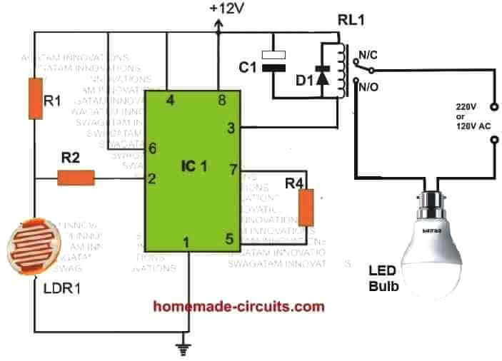
Circuit Diagram
How the IC 555 Street Light Circuit Works
The working of this circuit is very interesting because of how the 555 IC is wired. Let us understand step by step:
Daytime Operation: When bright sunlight falls on LDR, then its resistance is very low.
This low resistance pulls pin 2 of IC 555 down to ground level (below 1/3 of supply voltage).
Because pin 2 gets a low trigger pulse, the output at pin 3 of the 555 IC goes HIGH. When pin 3 is high, then transistor T1 stays turned OFF, relay remains de energized and your street light bulb stay switched OFF.
Nighttime Operation: When evening arrives and light decreases, then the LDR resistance goes very high.
This high resistance stop the ground connection and allow a positive potential to develop on pin 2 of the 555 IC via resistor R1. As soon as the voltage at pin 2 goes above the internal threshold, the IC output at pin 3 drops to LOW.
Relay Activation: When pin 3 goes low, then transistor T1 get proper base bias current and switches ON.
Relay clicks and activate, shifting its contacts to the Normally Open (N/O) position and your street light bulb turns ON automatically.
Hysteresis and Delay: The circuit include a small resistor connected between pin 5 and 7 to control hysteresis which prevents the circuit from getting confused by passing car headlight or brief shadow.
Also the combination of R2 and C1 ensure a small 2 second time delay so the relay does not react instantly to lightning or sudden camera flashes.
Detailed Working Explanation
During day time when there's ample light on the LDR, the LDR resistance is low, which keeps the pin#2 to ground level causing the output pin#3 potential to be high.
This causes the relay to remain switched OFF with its contacts held at N/C. This in turn causes the light bulb to remain switched OFF.
When night sets in, the light on the LDR decreases causing its resistance to increase. This causes a positive potential to develop on pin#2 of the IC 555, via R1. Due to this pin#3 turns negative triggering ON the relay. The relay contacts now shift towards the N/O turning ON the lamp.
The 555 IC is used as a comparator in this circuit, rather than as an astable or monostable multivibrator. To understand this fairly uncommon use, it's important to understand how a 555 works in general: When input pin 2 receives a trigger (low pulse), the output rises high. This low trigger pulse is defined as a voltage that is less than 1/3 of the supply voltage. When the voltage at the second input, pin 6, temporarily exceeds 2/3 of the supply level, the output goes low again.
Although the second input pin 6 is not used in this arrangement, the chip's output could still flip to the low state since pin 6 is linked directly to the positive supply rail.
By connecting a resistor between pins 5 and 7 of the 555, as illustrated in the circuit diagram the level of hysteresis can be controlled. The level of hysteresis is inversely related to the resistor value, with 100K being a good place to start for research. If R1 is replaced with an 1M potentiometer or preset, the circuit's responsiveness could be adjusted.
Theoretically, the circuit's supply voltage has to be equal to the relay's coil voltage. Nevertheless, do not use more than 16 V since the 555 could well be damaged. At a supply voltage of 12 V, the circuit's current usage, excluding the relay, is 4 mA. The components R2 and C1 guarantee that the relay is powered after a delay of around 2 seconds, making the circuit insensitive to sudden changes in light intensity.
How to Set Up
This above explained IC 555 based automatic street light circuit can be set up with the help of the following points:
- Replace R1 with a 1M preset. Keep its wiper fully towards the positive line.
- Cover the LDR with an opaque shield.
- Next, illuminate the area with the amount of light at which the relay changeover is required to take place.
- Switch ON power, and remove the cover from the LED.
- Now adjust the preset R1 until the lamp just switches OFF.
- Your circuit is set now.
After this, try covering the LDR with your finger and check the response, the relay sh
Step by Step Setup and Calibration Guide
After you solder all parts neatly on your PCB or general board, follow these simple step to set it up:
- If you want easy adjustment, then replace fixed resistor R1 with a 1M preset potentiometer.
- Turn its wiper fully towards the positive supply side, connect your 12V SMPS power supply to circuit input.
- Cover the LDR with your hand or an opaque card to simulate evening darkness.
- Now adjust your preset R1 very slowly until you hear the relay click and 220V LED bulb turns ON.
- Remove your hand from the LDR to let room light fall on it and the bulb should turn OFF instantly.
- After you get the correct setting, apply a small drop of nail polish or glue on preset so it stay fixed permanently.
Important Hardware & Pinout Reminder
IC 555 Pin Connections: Be very careful when inserting the 555 IC into its holder then.
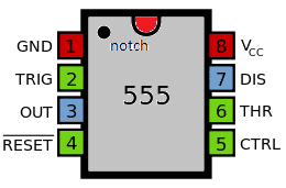
Pin 1 goes to ground, Pin 8 goes to the positive 12V rail, Pin 2 is your trigger input connected to the LDR divider and Pin 3 is the output going to the transistor base resistor.
Diode Protection: Always make sure diode D1 (1N4007) is connected in reverse bias across the relay coil terminal to protect transistor T1 from high voltage spike when relay turns off then.
Troubleshooting Tip for IC 555 Automatic Street Light Circuit
Relay is Clicking or Blinking Continuously in Evening:
Cause: This happens because of optical feedback.
If the light from your 220V street bulb fall directly onto the LDR sensor, then circuit gets confused. It thinks day has come back, turns off the bulb and then instantly turns it back on when darkness returns then.
Solution: Always mount your LDR facing upward toward the open sky or inside a small dark plastic visor/shield so that light from street bulb can never touch the LDR surface.
Relay Does Not Turn ON Even in Complete Darkness:
Cause: The preset potentiometer (R1) is set incorrectly, or the transistor (BC547) / relay connection have a wiring mistake.
Solution: First, check if pin 3 of 555 IC is going to low state when you cover LDR then.
If pin 3 goes low but the relay does not click, then check your BC547 transistor pinout (Collector, Base, Emitter) and make sure relay coil is getting proper 12V supply. Adjust preset R1 slowly until the relay clicks.
Relay Makes a Buzzing Sound:
Cause: Low supply voltage or weak current from your 12V SMPS adapter.
Solution: Make sure your 12V power supply adapter can provide at least 500mA to 1 Amp of steady current. Check filter capacitor C1 (220uF) to make sure it is not weak or damaged.



Need Help? Please Leave a Comment! We value your input—Kindly keep it relevant to the above topic!