In this artice we are going to learn how to build a very simple and cheap automatic street light circuit using only a single transistor. If you are a beginner in electronics and you want to make an automatic lamp that turns on by itself during evening and turns off in morning without any manual switch, then this step-by-step guide is specially for you.
Why Choose a Single Transistor Street Light Circuit?
When starting out in electronics hobby, many students and beginners look for circuits that do not require complicated integrated circuits or microcontrollers.
This single transistor automatic street light circuit is the best choice because it uses very basic and easily available components like resistors, an LDR, a BC547 transistor, and a 12V relay.
Even if you are making your very first electronics project on a general PCB or breadboard, you can easily assemble this circuit within a short time.
Circuit Diagram
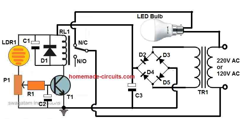
Required Parts List
To build this single transistor automatic street light circuit, you will need the following electronic components:
- R1 = 1K ohm resistor (1/4 watt, 5% CFR)
- P1 = 10K preset potentiometer
- LDR1 = Any standard Light Dependent Resistor (LDR)
- C1 = 220uF / 25V electrolytic capacitor
- C2 = 10uF / 25V electrolytic capacitor
- C3 = 1000uF / 25V electrolytic capacitor
- D1 to D5 = 1N4007 diodes (used for bridge rectifier and protection)
- T1 = BC547 NPN transistor
- TR1 = 0-12V, 500mA or 1 Amp step-down transformer (Note: You can also replace the transformer, bridge rectifier, and C3 capacitor with a ready-made 12V SMPS power supply adapter if you want a simpler power input)
- RL1 = 12V relay (200 to 400 ohm coil resistance)
- LED Bulb = 220V or 120V LED bulb (100 watt or as per your street light requirement)
Important Safety Warning Regarding AC Mains
Before you start wiring or testing this circuit, please remember that this project deals with high voltage AC main (220V or 120V) through the relay contacts to power the street light bulb.
Working with AC main can be extremely dangerous and can cause severe electric shocks or fatal accidents if proper care is not taken then.
Always keep the power disconnected while soldering or making wiring changes, use insulated tool and enclose the final circuit safely inside a well insulated plastic junction box so that no bare AC wires are left exposed.
How the Single Transistor Circuit Works
The working of this circuit is very easy to understand once you know how an LDR and an NPN transistor behave.
During daytime, bright sunlight falls on the LDR. Because of the bright light, the internal resistance of the LDR becomes very low. Due to this low resistance, the voltage at the base of transistor T1 is kept at a high level (around 0.6V or more). Because the base gets proper positive bias voltage, the BC547 transistor remains switched ON.
When the transistor is ON, current flows through its collector terminal, which keeps the 12V relay activated. When the relay is energized, its internal contact shifts to the Normally Open (N/O) position.
Since your 220V lamp is connected to the Normally Closed (N/C) position of the relay, the lamp stays switched OFF during the entire daytime.
Now, when evening arrives and natural daylight starts fading, the light falling on the LDR decreases. As the light goes down, the resistance of the LDR starts increasing heavily. This high resistance stops the positive bias voltage from reaching the transistor base via preset P1, causing the base potential to drop.
When the transistor base voltage drops below 0.6V, transistor T1 switches OFF. As soon as the transistor turns off, the collector current stops, and the relay is de-energized.
The relay switch contacts return to their default Normally Closed (N/C) position. This action completes the AC mains circuit for your light bulb, and the street light turns ON automatically.
The next morning, when the sun rises again and light falls on the LDR, the whole cycle repeats in reverse, turning the lamp OFF automatically. The small capacitors connected at the circuit stages ensure that during twilight or evening transition times, the relay does not click rapidly or chatter.
Important Hardware & Pinout Reminders
Transistor Pinout: Always check the pin configuration of your BC547 NPN transistor carefully before soldering.
Looking at the flat side of the transistor with the pins pointing down, the left pin is Collector, middle pin is the Base and right pin is the Emitter.

Connecting these incorrectly can damage the transistor.
Relay Flyback Diode: Make sure diode D5 (1N4007) is connected in reverse bias across the two coil terminals of your 12V relay.
This freewheeling diode is very important because it absorbs high voltage back EMF spike created when the relay coil switches off, then protecting your BC547 transistor from burning out.
Step-by-Step Setup and Calibration Guide
Once you solder all components carefully according to circuit diagram, you need to set up and calibrate the preset potentiometer so it triggers at the correct darkness level:
- First keep wiper of preset P1 fully towards the ground level position.
- Switch ON your 12V power supply to the circuit.
- Expose the LDR to the exact amount of ambient light or evening dimness at which you want your street light to switch ON.
- Now very slowly adjust the 10K preset P1 until you hear the relay click and activate.
- Once you find the exact trigger point, apply a small drop of glue or nail polish on the preset knob so it never moves due to wind or vibration.
- Test your setup by covering the LDR completely with your hand or an opaque card. You will see 220V LED bulb turn on instantly, and when you remove your hand, then bulb will turn off.
Important Troubleshooting Tips
- Watch out for optical feedback: Make sure the light from your controlled street bulb never falls directly onto the LDR sensor. If bulb light falls on the LDR, then circuit will get confused, thinking daytime has returned, turning off the lamp and creating an endless blinking loop. Always install the LDR facing upward to the open sky or inside a protected shield.
- Power supply check: If you are using a 12V SMPS adapter instead of a transformer and bridge rectifier, then make sure the positive and negative connections are properly matched before powering on the circuit.
Conclusion
The working of the circuit is simple. During day time when the ambient light is sufficiently high, the LDR has a low resistance. Due to this low resistance it keeps the transistor base more towards the positive level, causing the transistor base at the required 0.6V. The transistor therefore remains switched ON.
With the transistor in the switched ON condition, the relay also remains activated with its contacts resting on the N/O position.
Since the lamp is connected at the N/C position of the relay, the lamp remains switched OFF.
Now when the ambient light begins to fall during evening and finally reaches a level where the resistance of the LDR increases adequately, the ground potential on the transistor base is raised via the P1, cutting off the biasing potential to the base.
When this happens, the transistor is eventually switched ON. When the transistor is switched ON, its collector becomes active and it deactivates the relay. The relay contacts change from its initial N/O position to the N/C position.
This allows the current to flow through the lamp, and the lamp illuminates.
The next morning, when the ambient light level on the LDR increases, the lamp is switched off yet again, and the cycle repeats itself everyday.
The capacitors at the base of the transistor and the relay ensure that during the transition periods (twilight) or the trip points, the relay contacts do not chatter, rather changeover smoothly.
The potentiometer or the preset can be set appropriately to determine at what light levels the relay is switched ON and OFF.
By following this simple guide, you can successfully build your very own single transistor automatic street light circuit at home.


Need Help? Please Leave a Comment! We value your input—Kindly keep it relevant to the above topic!